1. Overview
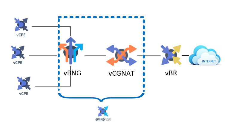
The goal of this usecase is to explain how we can configure a 6wind VSR to play the role of BNG and CGNAT at the same time. It can be a typical BNG/CGNAT scenario for a common broadband ISP.
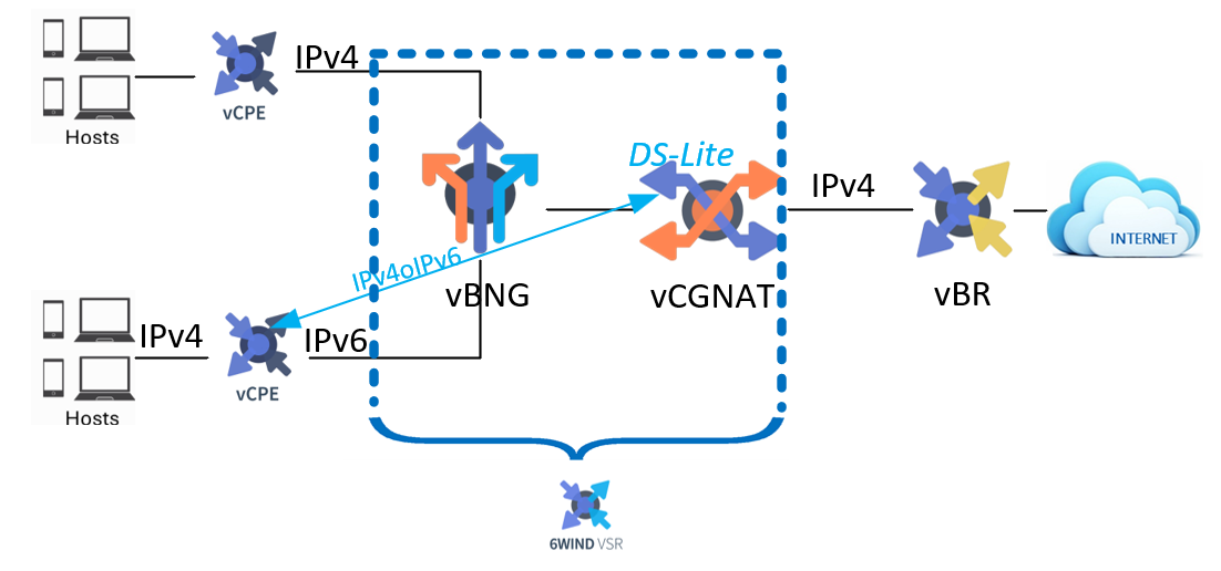
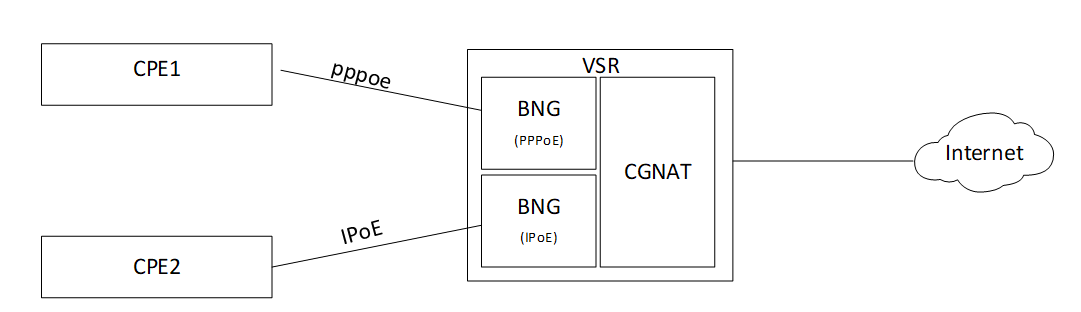
For BNG we will deploy both PPPoE and IPoE tunnels, using IPv4 core network for PPPoE and IPv6 core network for IPoE. Then finally handling IPv4 flows with a CG-NAT DS-Lite box (4in6).
Thus BNG-CG-NAT will be managed by a Virtual Service Router, which will be installed onto a proxmox hypervisor, avoiding deployment of multiple VMs or physical appliances. Of course this is only an example and you are totally free to use your own hypervisor (vmware/etc…).
Finally, we’ll learn how to activate QoS or traffic-limiting and KPI.
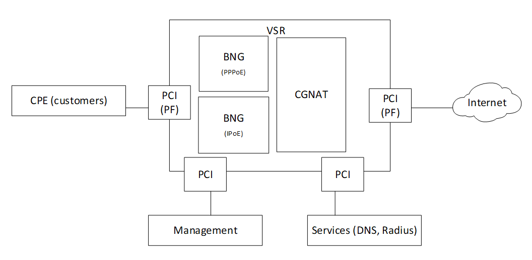
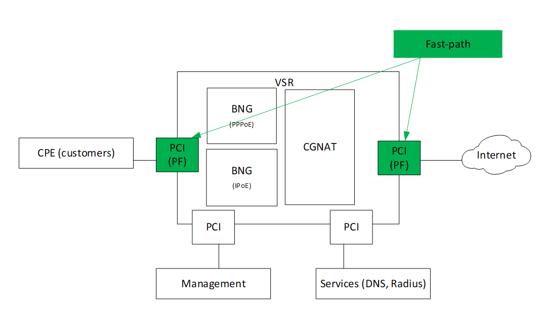
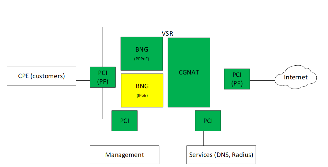
Consequently, we’ll build following topology, using two different physical NIC.
We will use DS-Lite (4in6) to handle IPv4 flows coming over IPv6 core network.
We will use proxmox hypervisor to create the VM for Virtual Service Router which will combine BNG and CGNAT functions. Finally we will configure three functions on Virtual Service Router: - BNG (PPPoE) - BNG (IPoE) - CGNAT
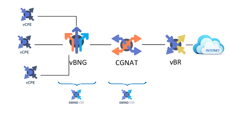
For information, there is another usecase “BNG full deployment guide with Proxmox”, where BNG and CGNAT are installed on different Virtual Service Router.
2. Install a VM VSR using Proxmox VE
This chapter explains how to start a Virtual Service Router VM using Proxmox VE and the .iso file. It expects that you already installed a Proxmox VE cluster, in which you are able to spawn VMs with network connected. This document will guide you through the required steps needed to provision your Proxmox hypervisor. It follows the following steps:
Prepare the host for high performance
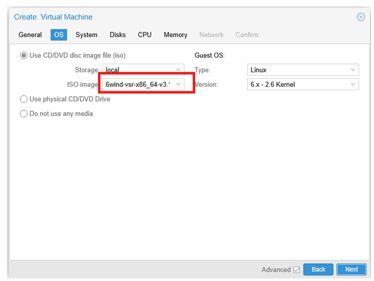
Make the .iso file available to Proxmox VE
Create and configure a VM
Boot the VM using the .iso file
install Virtual Service Router on the virtual disk
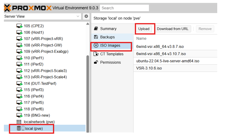
Upload the .iso file
Select the local storage of your node in the left pane and visualize its content:
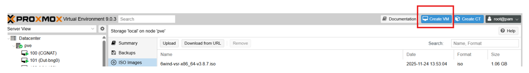
2.1. Create and boot the VM
Right clik on your proxmox server name, then press the Create VM button to launch the creation wizard.
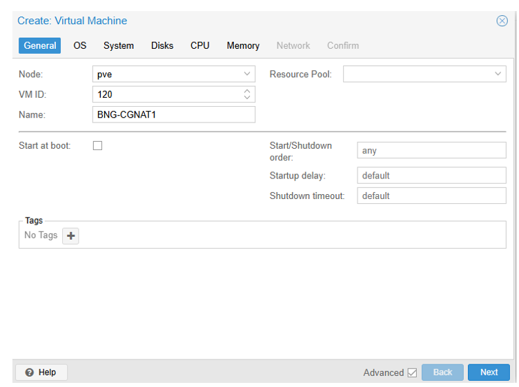
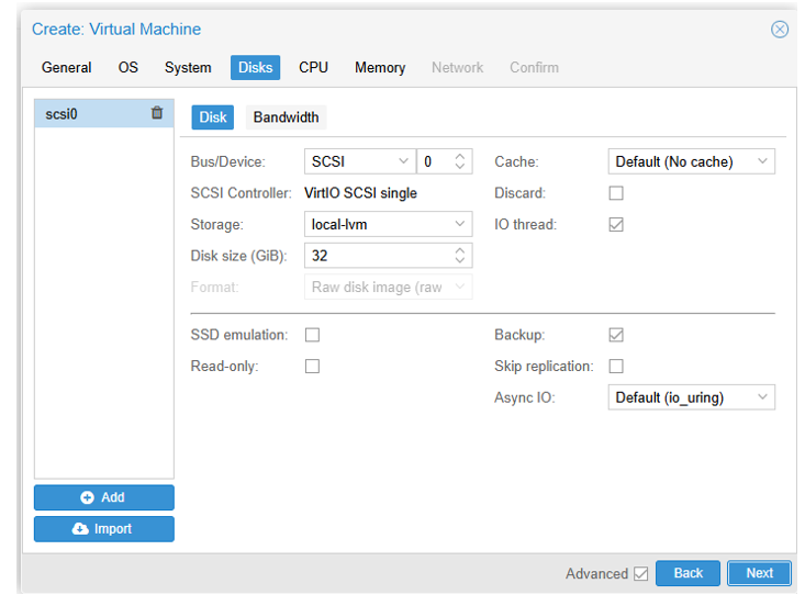
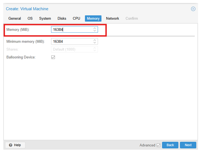
- VM BNG CGNAT requirements :
RAM : 16 GB
CPU Cores : 16 (8 physical cores so 16 vCPUs)
VirtIO Interface : 2 (1 for management, 1 for radius connectivity)
VF or PF: 2 ( in our example I assigned 2 PFs: eno1 and eno2)
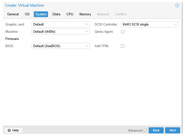
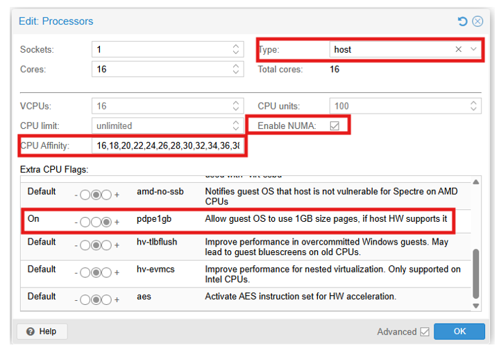
2.6. Step 5 : CPU
In CPU tab, allocate at least 16 cores on 1 socket and select host as CPU type, it is also the right time to specify the CPU affinity, if you need to dedicate some CPUs to your new VM. There is another way to isolate some CPU to your VM, the procedure will be described in the step 10.
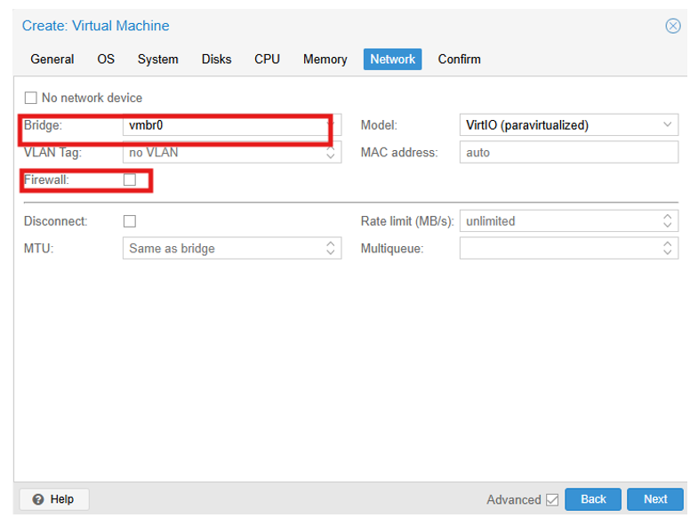
2.8. Step 7: Network
In Network tab, bind the virtual management interface to a host bridge in order to have access to external network (usually vmbr0). Select VirtIO as model type, untick Firewall then press Next:
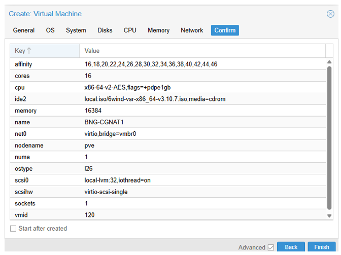
2.9. Step 8: confirmation
In Confirm tab, review your settings and press Finish to finalize the creation and get back to the main dashboard:
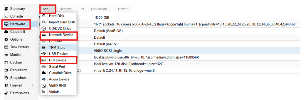
2.10. Step 9: Assign network interfaces
In addition to the management interface we need an interface to join services like DNS, Radius etc.. and we need two interfaces, one for Internet and another for internal network CPEs (customers).
So click on your VM name, then “Hardware”, click “Add” then “PCI Device” : we need two PCI (PF) and we can add also a network interface for Services.
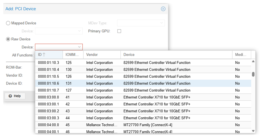
2.11. Step 10: Focus on CPU Affinity for maximal performance
To get better performance, we can assign to the new VM, CPUs and PCIs managed by the same NUMA. To check the topology of the host we can log into Proxmox server by ssh and use the commands “lstopo” and “lscpu | grep NUMA” or “numactl -H”.
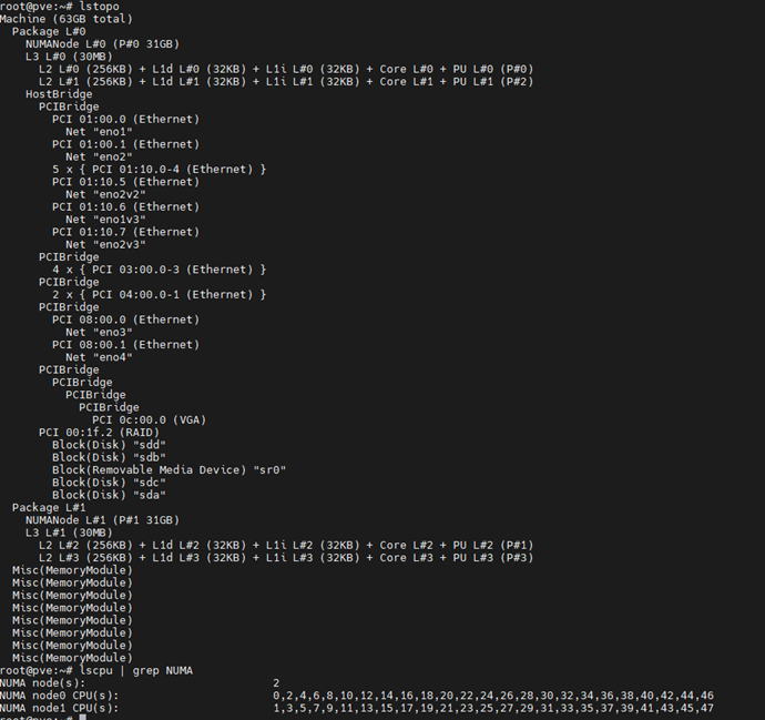
So we can see that PCIs are managed by numa0, so we can assign CPUs from this numa to our VM. For example, here, DO NOT give core 6-21 to the VM, as they will be spanned across two different physical nodes (0 and 1), hence reducing the performance. So you can assign CPUs “16,18,20,22,24,26,28,30,32,34,36,38,40,42,44,46”.
CPU isolation: to get also better performance, you can isolate CPUs used by the system from those used by VMs and containers. Here is an example to allocate CPUs 0 to 3 to the system and keep CPUs 4 to 47 to machines. And also you can exclude CPUs given to your VM “16,18,20,22,24,26,28,30,32,34,36,38,40,42,44,46” from those given to for other VMs and containers.
systemctl set-property --runtime -- user.slice AllowedCPUs=0-3
systemctl set-property --runtime -- system.slice AllowedCPUs=0-3
systemctl set-property --runtime -- init.scope AllowedCPUs=0-3
systemctl set-property --runtime machine.slice AllowedCPUs=4-15,17,19,21,23,25,27,29,31,33,35,37,39,41,43,45,47
You can also use this command to assign CPUs to your VMs:
- For the VM of BNG (replace 119 by your VM PID number)
taskset --cpu-list --all-tasks --pid 16,18,20,22,24,26,28,30,32,34,36,38,40,42,44,46 "$(< /run/qemu-server/119.pid)"
2.11.1. Set CPU Isolation persistent
Here, we will give an example how we can configure a service in the proxmox host to apply the CPU configuration described above. Without those actions, the default CPU configuration will be applied at each reboot.
To proceed we’ll create a fake service that will automatically set CPU isolation.
Edit the following file:
root@rome:~# vi /etc/systemd/system/cpu-isolation.service
Then populate it according to your needs and start the service:
[Unit]
Description=Script to enable SR-IOV on boot

[Service]
Type=oneshot

ExecStart=/usr/bin/bash -c 'systemctl set-property --runtime -- user.slice AllowedCPUs=0-3'
ExecStart=/usr/bin/bash -c 'systemctl set-property --runtime -- system.slice AllowedCPUs=0-3'
ExecStart=/usr/bin/bash -c 'systemctl set-property --runtime -- init.scope AllowedCPUs=0-3'
ExecStart=/usr/bin/bash -c 'systemctl set-property --runtime machine.slice AllowedCPUs=4-15,17,19,21,23,25,27,29,31,33,35,37,39,41,43,45'
ExecStart=/usr/bin/bash -c 'taskset --cpu-list  --all-tasks --pid  16,18,20,22,24,26,28,30,32,34,36,38,40,42,44,46 "$(< /run/qemu-server/119.pid)"'


[Install]
WantedBy=multi-user.target
root@rome:~# systemctl enable cpu-isolation.service root@rome:~# systemctl start cpu-isolation.service
If the service starts without issues you should get such output :
root@rome:~# systemctl status cpu-isolation.serviceo cpu-isolation.service - Script to apply CPU Isolation configuration Loaded: loaded (/etc/systemd/system/cpu-isolation.service; enabled; preset: enabled) Active: inactive (dead) since Mon 2026-02-23 17:07:52 CET; 3min 43s ago Invocation: 06002d5875b142eca64be7f5489e6129 Process: 2689866 ExecStart=/usr/bin/bash -c systemctl set-property --runtime -- user.slice AllowedCPUs=0-3 (code=exited, status=0/SUCCESS) Process: 2689867 ExecStart=/usr/bin/bash -c systemctl set-property --runtime -- system.slice AllowedCPUs=0-3 (code=exited, status=0/SUCCESS) Process: 2689869 ExecStart=/usr/bin/bash -c systemctl set-property --runtime -- init.scope AllowedCPUs=0-3 (code=exited, status=0/SUCCESS) Process: 2689872 ExecStart=/usr/bin/bash -c systemctl set-property --runtime machine.slice AllowedCPUs=4-15,17,19,21,23,25,27,29,31,33,35,37,39,41,43,45 (code=exited, status=0/SUCCESS) Process: 2689874 ExecStart=/usr/bin/bash -c taskset --cpu-list --all-tasks --pid 16,18,20,22,24,26,28,30,32,34,36,38,40,42,44,46 "$(< /run/qemu-server/120.pid)" (code=exited, status=0/SUCCESS) Main PID: 2689874 (code=exited, status=0/SUCCESS) Mem peak: 2.2M CPU: 65ms
2.12. Install Virtual Service Router
Warning
Please carefully check the device associated to the disk you want to use, or you could wipe the wrong drive in the next step. When following this installation guide you have only one disk attached to the VM. Thus the device name is sda. If you attach additional virtual disks, make sure to choose the right device.
Warning
Please make sure that there is no other Virtual Service Router live CDROM or live USB inserted in this VM. Otherwise the system might fail to boot properly.Press Start in the top right corner to actually start the VM.
Note
Please make sure to select this disk as boot device after installation. You can access boot menu by pressing ESC at startup in the VM console. Once the VM has booted on the .iso file, select it in the left pane of the main dashboard and press the >_ Console button to get access to the serial console .
Log in as admin, password admin, and at the prompt, do:
vsr> cmd system-image install-on-disk sda
This command will install Virtual Service Router on /dev/sda. The relevant configuration files will be copied to the local drive. Reboot to finally boot Virtual Service Router from the virtual hard disk:
vsr> cmd reboot
2.13. Configuration
2.13.1. General configuration - Hostname
vsr> edit running
vsr# / system hostname vBNG-CGNAT
vsr# commit
2.13.2. management vrf
It is recommended to create a dedicated vrf for management and assign the management interface to it. When configuring physical interface if you need to check which port name is related to which PCI assigned to the VM, you can use this command “show state network-port”, you will find the mac address of the interface and a description with the vendor and model, example:
vBNG-CGNAT# show state network-port
network-port pci-b0s18
 bus-addr 0000:00:12.0
 vendor "Red Hat, Inc."
 model "Virtio network device"
 mac-address bc:24:11:01:71:2f
 type physical    ..
vBNG-CGNAT#  / vrf mgmt interface physical mgmt0 ipv4 dhcp
vBNG-CGNAT#  / vrf mgmt interface physical mgmt0 port pci-b0s18
vBNG-CGNAT#  / vrf mgmt ssh-server
2.13.3. License
vBNG-CGNAT# / system license online serial abxxxxx-xxxxx-xxxxx
if we reach license server via management interface we need to mention this in the configuration of the license.
vBNG-CGNAT# / system license online vrf mgmt
2.13.4. Fast-path settings
In fastpath we need only to assign PCIs which will forward traffic from CPEs to internet.
vBNG-CGNAT#  / system fast-path port pci-b0s16
vBNG-CGNAT#  / system fast-path port pci-b0s17
In order to be able to get 10000 sessions, it is mandatory to update some Fast-Path parameters : As each PPP session is done on a dedicated PPP interface hosted by the Fast-Path, increasing the maximum number of interfaces and PPPoE sessions accepted by the FP is mandatory :
vBNG-CGNAT# / system fast-path limits fp-max-if 10300
vBNG-CGNAT# / system fast-path limits pppoe-max-channel 10300
vBNG-CGNAT# / system fast-path limits ip4-max-addr 10300
vBNG-CGNAT# / system fast-path limits ip6-max-addr 10300
3. Configure BNG functions and CGNAT
3.1. Configure PPPoE
3.1.1. Interfaces
- To CPEs:
vBNG-CGNAT# / vrf main interface physical to-CPEs port pci-b0s16- To Internet:
vBNG-CGNAT#  / vrf main interface physical to-internet ipv4 address 10.100.10.1/29
vBNG-CGNAT#  / vrf main interface physical to-internet port pci-b0s17
- We need a default route to internet
vBNG-CGNAT# / vrf main routing static ipv4-route 0.0.0.0/0 next-hop 10.100.10.2- To Services:
vBNG-CGNAT#  / vrf main interface physical to-Services ipv4 address 172.20.1.1/24
vBNG-CGNAT#  / vrf main interface physical to-Services port pci-b0s19
3.1.2. Configure PPPoE Server
We will define a maximum of 10000 sessions that will be given an IP in the 100.64.0.0/16 pool (From IPv4 prefix for shared address space 100.64.0.0/10 RFC 6598). Finally we set the dns server that will be sent to CPE. Let’s bind the PPP server to interface to-CPEs:
Note
In this example we use 100.64.0.0/16 as source IPs, but you can use any other range from RFC 1918.
vBNG-CGNAT# / vrf main ppp-server instance pppoe-server pppoe enabled true
vBNG-CGNAT# / vrf main ppp-server instance pppoe-server ppp ipcp require
vBNG-CGNAT# / vrf main ppp-server instance pppoe-server ip-pool default-local-ip 100.64.255.254
vBNG-CGNAT# / vrf main ppp-server instance pppoe-server ip-pool pool pppoe peer-pool 100.64.0.0/16
vBNG-CGNAT# / vrf main ppp-server instance pppoe-server pppoe ip-pool pppoe
vBNG-CGNAT# / vrf main ppp-server instance pppoe-server pppoe interface to-CPEs
vBNG-CGNAT# / vrf main ppp-server instance pppoe-server dns server 8.8.8.8
vBNG-CGNAT# / vrf main ppp-server instance pppoe-server dns server 9.9.9.9
Now we configure the authentication to be bound to a RADIUS, this one will be directly connected through interface to-Services previously configured.
vBNG-CGNAT# / vrf main ppp-server instance pppoe-server auth radius enabled true
vBNG-CGNAT# / vrf main ppp-server instance pppoe-server auth radius default-local-ip 100.64.255.254
vBNG-CGNAT# / vrf main ppp-server instance pppoe-server auth radius server address 172.20.1.10 auth-port 1812 acct-port 1813 secret 5ecret123
vBNG-CGNAT# / vrf main ppp-server instance pppoe-server auth radius source-ip 172.20.1.1
vBNG-CGNAT# / vrf main ppp-server instance pppoe-server auth radius nas
vBNG-CGNAT# / vrf main ppp-server instance pppoe-server auth radius nas ipv4-address 172.20.1.1
vBNG-CGNAT# / vrf main ppp-server instance pppoe-server auth radius nas identifier 172.20.1.1
vBNG-CGNAT# / vrf main ppp-server instance pppoe-server auth radius change-of-authorization-server
vBNG-CGNAT# / vrf main ppp-server instance pppoe-server auth radius change-of-authorization-server ip-address 172.20.1.10
vBNG-CGNAT# / vrf main ppp-server instance pppoe-server auth radius change-of-authorization-server secret 5ecret123
We set the accounting interval to 300s which is a good balance between getting frequent accounting, and the load is will induce to PPP process. The jitter is also configured at 180s, meaning the effective accounting packets will be sent every 300s +/- 180s, avoiding pikes in radius traffic. Those values can be modified according to your needs.
vBNG-CGNAT# / vrf main ppp-server instance pppoe-server auth radius accounting interim-interval 300
vBNG-CGNAT# / vrf main ppp-server instance pppoe-server auth radius accounting interim-jitter 180
vBNG-CGNAT# / vrf main ppp-server instance pppoe-server auth radius accounting session-id-in-authentication true
Now the PPPoE server is active, we can already check the current client sessions using this command :
vBNG-CGNAT running config# show ppp-server session instance pppoe-server
interface username mac address       ip address status uptime   l3vrf vlans
========= ======== ===========       ========== ====== ======   ===== =====
ppp0      cpe1     22:24:4b:e9:7e:c9 100.64.0.0 active 00:04:32
3.2. configure CGNAT
Lets now configure CGNAT function, to let pppoe users connect to Internet. I use here as example the range 192.168.168.8/29, which you should replace it by your public IP range. Below you’ll find the definition of a pool containing 6 IPv4 addresses, they will be shared accross all clients, each of them will receive 32 ports dynamically allowed.. Note Here we see the matching between the fast-path limits we modified earlier, /29 allows 6 IP to be used and the block-size we attribute to each user is 32 ports.
vBNG-CGNAT# / vrf main cg-nat
vBNG-CGNAT# / vrf main cg-nat pool mypool
vBNG-CGNAT# / vrf main cg-nat pool mypool address 192.168.168.8/29
Dont forget to Replace pool addresses with your public IP range.
vBNG-CGNAT# / vrf main cg-nat pool mypool allocation-mode
vBNG-CGNAT# / vrf main cg-nat pool mypool allocation-mode dynamic-block
vBNG-CGNAT# / vrf main cg-nat pool mypool allocation-mode dynamic-block block-size 32
vBNG-CGNAT# / vrf main cg-nat rule 1 dynamic-snat44 match source
vBNG-CGNAT# / vrf main cg-nat rule 1 dynamic-snat44 match source-address 100.64.0.0/16
vBNG-CGNAT# / vrf main cg-nat rule 1 dynamic-snat44 match outbound-interface to-internet
vBNG-CGNAT# / vrf main cg-nat rule 1 dynamic-snat44 translate-to
vBNG-CGNAT# / vrf main cg-nat rule 1 dynamic-snat44 translate-to pool-name mypool
To test you can ping internet address from the CPE and check cgnat statistics by using this command:
vBNG-CGNAT running config# show cg-nat pool-statistics pool-name mypool
block-usage: 8 ips (non empty = 1, ratio 12.50%), blocks used per ip: min = 1, max = 1, average = 1.00
     1 ip (100.00%) have 1 block used
3.3. Configure IPoE Server
Now if we need to support IPoE in the network we can configure IPoE server.
- For IPoE we will use IPv6 range with dhcp ip pool fc00:0:1::1/64.
vBNG-CGNAT# / vrf main interface physical to-CPEs ipv6 address fc00:0:1::1/64
vBNG-CGNAT# / vrf main ipoe-server enabled true
vBNG-CGNAT# / vrf main ipoe-server limits max-session 10000
vBNG-CGNAT# / vrf main ipoe-server dhcpv6-server ip6-pool poolCPE
vBNG-CGNAT# / vrf main ipoe-server dhcpv6-server ip6-pools-setup pool poolCPE prefix fc00:0:1::/48 prefix-len 64
vBNG-CGNAT# / vrf main ipoe-server dhcpv6-server ip6-dns server 8::8
vBNG-CGNAT# / vrf main ipoe-server dhcpv6-server ip6-dns server 9::9
We set the lease to be valid between 3000 & 3600s, the server ID is mandatory, it will be based on a DUID-Link Layer format :
vBNG-CGNAT# / vrf main ipoe-server dhcpv6-server lease pref-lifetime 3000
vBNG-CGNAT# / vrf main ipoe-server dhcpv6-server lease valid-lifetime 3600
vBNG-CGNAT# / vrf main ipoe-server dhcpv6-server server-id 1:0:0:1
- Finally we also set a delegated-prefix pool for host behind the CPE.
vBNG-CGNAT# / vrf main ipoe-server dhcpv6-server ip6-pools-setup prefix-delegation cpePD
vBNG-CGNAT# / vrf main ipoe-server dhcpv6-server ip6-pools-setup prefix-delegation cpePD prefix 2000:0:1:100::/60
vBNG-CGNAT# / vrf main ipoe-server dhcpv6-server ip6-pools-setup prefix-delegation cpePD prefix-len 64
vBNG-CGNAT# / vrf main ipoe-server dhcpv6-server ipv6-prefix-delegation cpePD
- We’ll also bind the IPoE server to interface to-CPEs :
vBNG-CGNAT# / vrf main ipoe-server dhcpv6-server interface to-CPEs
Now we configure the authentication to be bound to a RADIUS, this one will be directly connected through interface to-Services previously configured. Regarding authentication we’ll use following criterias (username/password will be identicals) :
Interface where the IPoE sessions (DHCP packets) are coming from
Client MAC address
Note
Depending on your environment you are free to use following options :
{server_interface} : Interface’s name receiving DHCP packet.
{agent_remote_id} : Agent remote ID (option 82 sub-option 2 for DHCPv4, option 37 for DHCPv6).
{circuit_id} : Agent circuit ID (option 82 sub-option 1).
{client_hwaddress}: Peer hardware (MAC) address.
{client_tagX_vlan_id}/{client_tagX_qinq_id} : VLAN or QINQ id in decimal, where X is the VLAN or QINQ order in the Ethernet frame. It starts at 1 which is the order of the outer tag.
vBNG-CGNAT# / vrf main ipoe-server auth
vBNG-CGNAT ipoe-server# username {server_interface}_{client_hwaddress}
vBNG-CGNAT ipoe-server# password {server_interface}_{client_hwaddress}
vBNG-CGNAT ipoe-server# radius server address 172.20.1.10 auth-port 1812 acct-port 1813 secret 5ecret123
vBNG-CGNAT ipoe-server# radius nas ip-address 172.20.1.1
vBNG-CGNAT ipoe-server# radius nas identifier 172.20.1.1
vBNG-CGNAT ipoe-server# radius change-of-authorization-server ipv4-address 172.20.1.10
vBNG-CGNAT ipoe-server# radius change-of-authorization-server secret 5ecret123
vBNG-CGNAT ipoe-server# radius accounting interim-interval 300
vBNG-CGNAT ipoe-server# radius accounting interim-jitter 180
vBNG-CGNAT ipoe-server# radius accounting session-id-in-authentication true
- To check IPoE session please use this command:
vBNG-CGNAT> show ipoe-server session
interface username                  mac address       ip address                     status uptime   l3vrf vlans server
========= ========                  ===========       ==========                     ====== ======   ===== ===== ======
ipoe0     to-CPEs_86:51:36:7f:71:58 86:51:36:7f:71:58 fc00:0:1:0:8451:36ff:fe7f:7158 active 00:00:32
3.4. Configure DS-Lite between BNG and CPEs
3.4.1. Configure DS-Lite interfaces
Finally we use IPIP interfaces, they are intended to encapsulate IP packets, so here we will encapsulate all IPv4 traffic into IPv6 packets, then the IPv6 will be removed and natted according cg-nat configuration we’ll see later
vBNG-CGNAT# / vrf main interface ipip aftr1
vBNG-CGNAT# / vrf main interface ipip aftr1 local fc00:0:1::1
vBNG-CGNAT# / vrf main interface ipip aftr1 remote ::
vBNG-CGNAT# / vrf main interface ipip aftr1 link-interface to-CPEs
vBNG-CGNAT# / vrf main interface ipip aftr1 ds-lite-aftr true
3.4.2. Configure CGNAT to accept IPv4 traffic from IPoE clients
- Regarding IPoE traffic, the source address of the IPv4 packets can be anything, meaning we accept every host that can be behind a CPE behind IPoE traffic. We also add the outbound interface as a matching criteria.
vBNG-CGNAT# / vrf main cg-nat rule 2 dynamic-snat44 match source-address 0.0.0.0/0
vBNG-CGNAT# / vrf main cg-nat rule 2 dynamic-snat44 match outbound-interface to-internet
Now we also specify the softwire address for rule 2, which means the IP attributed to the CPE by the BNG. As we saw, depending on the BNG, attributed IP’s will be within a dedicated /48 pool, so here we specify our three possible /48 where the cg-nat process will be able to extract and handle packets.
vBNG-CGNAT# / vrf main cg-nat rule 2 dynamic-snat44 match ds-lite
vBNG-CGNAT# / vrf main cg-nat rule 2 dynamic-snat44 match ds-lite softwire-address fc00:0:1::/48
vBNG-CGNAT# / vrf main cg-nat rule 2 dynamic-snat44 translate-to
vBNG-CGNAT# / vrf main cg-nat rule 2 dynamic-snat44 translate-to pool-name mypool
3.4.3. Limiting accepted sessions per second
Once done we’ll limit the amount of sessions accepted per second, as it can lead to overload the PPP server.
A Number of “starting” session increasing constantly is a sign of overload of the control plane daemon. This setting has direct impact on the “starting” counter, see below.
The right number can differ according to your BNG capacities (number of CPU given to control plane), here we’ll take the minimum case:. We recommend setting this value between 750 and 1500.
vBNG-CGNAT running config# / vrf main ppp-server instance pppoe-server max-starting 1000
vBNG-CGNAT running instance pppoe-server# show ppp-server statistics instance pppoe-server
     Sessions counters
      active    : 6153
  --> starting  : 321 <--
      finishing : 0

     PPPoE counters
      active        : 6474
      starting      : 0
      PADI received : 53394
      PADI dropped  : 0
      PADO sent     : 14119
      PADR received : 73298
      PADS sent     : 6474
See also
See the User’s Guide for more information regarding:
4. QoS
The following configuration has been used to define the 6WIND-qos-template used in our setup.
We’ll configure QoS based on a interface that can go up to 10Gb/s, we divide those 10G into two differents queues, first one for premium and other one for non-premium clients which will be the default queue for non authenticated or unmatched traffic. Premium clients will share 8G of reserved bandwith, with a maximum of 10G if available. Non-Premium will share 1G, with a maximum of 2G if available.
4.1. Configure a base static scheduler
vBNG-CGNAT# / qos scheduler scheduler-1
vBNG-CGNAT# / qos scheduler scheduler-1 htb
vBNG-CGNAT# / qos scheduler scheduler-1 htb default-queue 3
vBNG-CGNAT# / qos scheduler scheduler-1 htb queue 1
vBNG-CGNAT# / qos scheduler scheduler-1 htb queue 1 bandwidth 10G
vBNG-CGNAT# / qos scheduler scheduler-1 htb queue 1 ceiling 10G
vBNG-CGNAT# / qos scheduler scheduler-1 htb queue 1 child-queue 2
vBNG-CGNAT# / qos scheduler scheduler-1 htb queue 1 child-queue 3
vBNG-CGNAT# / qos scheduler scheduler-1 htb queue 2
vBNG-CGNAT# / qos scheduler scheduler-1 htb queue 2 description "This is the static parent queue for premium subscribers queues"
vBNG-CGNAT# / qos scheduler scheduler-1 htb queue 2 bandwidth 8G
vBNG-CGNAT# / qos scheduler scheduler-1 htb queue 2 ceiling 10G
vBNG-CGNAT# / qos scheduler scheduler-1 htb queue 3
vBNG-CGNAT# / qos scheduler scheduler-1 htb queue 3 description "This is the static parent queue for non-premium subscribers queues"
vBNG-CGNAT# / qos scheduler scheduler-1 htb queue 3 bandwidth 1G
vBNG-CGNAT# / qos scheduler scheduler-1 htb queue 3 ceiling 2G
If we apply QoS we need to adjust fast-path parameters again :
- In most cases a QoS profile will be applied to each session. We take the example of 2 different typology of customers (premium / non premium customers) each with 2 classes of traffic which will need to be shaped at different bandwidth. In this case you need:
Scheduler is in charge of applying the QoS profile, there will be 1 scheduler per subscriber plus some margin in case of maximum sessions reached is a bit higher than 10000, it can happen if sessions are still negotiated while we reach effectively 10000.
Policies determine which action must be taken depending on the Policies selector match. Here we have two possible policies per user, including some margin : 21000
Queues correspond to the queues where each customer class of traffic will be sent. 2 queues are created in above example, adding margin once again : 50000
vBNG-CGNAT# / system fast-path limits qos-max-schedulers 10300
vBNG-CGNAT# / system fast-path limits qos-max-policies 21000
vBNG-CGNAT# / system fast-path limits qos-max-queues 50000
4.2. Add the base-scheduler to the PPP server interface
vBNG-CGNAT# / vrf main interface physical to-CPEs qos egress scheduler scheduler-1
Configure the Templates locally for PPPoE server The template will deployed within the PPP server configuration, this one will splitted into two different queues:
premium-subscribers
non-premium-subscribers
Then each queues will be splitted into two dynamic queues, each one will look for an internal firewall tag to be effectively used. In below examples, we reserve at least 2M for VoIP traffic, and 950M for standard traffic, this traffic will be measured according the global queue we definied previously : queue 2. This one define a maximum of 10G traffic, meaning that with below configuration we can have a maximum of 10 premium clients using their session at 100% (10 x ~1G) with standard traffic.
vBNG-CGNAT# / vrf main ppp-server instance pppoe-server qos
vBNG-CGNAT qos# template premium-subscribers scheduler-interface to-CPEs
vBNG-CGNAT qos# template premium-subscribers queue prem static-parent 2
vBNG-CGNAT qos# template premium-subscribers queue prem bandwidth 1G
vBNG-CGNAT qos# template premium-subscribers queue prem ceiling 1G
vBNG-CGNAT qos# template premium-subscribers queue prem-voip dynamic-parent prem
vBNG-CGNAT qos# template premium-subscribers queue prem-voip bandwidth 2M
vBNG-CGNAT qos# template premium-subscribers queue prem-voip ceiling 4M
vBNG-CGNAT qos# template premium-subscribers queue prem-voip mark 0x1
vBNG-CGNAT qos# template premium-subscribers queue prem-data dynamic-parent prem
vBNG-CGNAT qos# template premium-subscribers queue prem-data bandwidth 10M
vBNG-CGNAT qos# template premium-subscribers queue prem-data ceiling 950M
vBNG-CGNAT qos# template premium-subscribers queue prem-data mark 0x0

vBNG-CGNAT qos# template non-premium-subscribers scheduler-interface to-CPEs
vBNG-CGNAT qos# template non-premium-subscribers queue non-prem static-parent 3
vBNG-CGNAT qos# template non-premium-subscribers queue non-prem bandwidth 50M
vBNG-CGNAT qos# template non-premium-subscribers queue non-prem ceiling 100M
vBNG-CGNAT qos# template non-premium-subscribers queue non-prem-voip dynamic-parent non-prem
vBNG-CGNAT qos# template non-premium-subscribers queue non-prem-voip bandwidth 1M
vBNG-CGNAT qos# template non-premium-subscribers queue non-prem-voip ceiling 2M
vBNG-CGNAT qos# template non-premium-subscribers queue non-prem-voip mark 0x1
vBNG-CGNAT qos# template non-premium-subscribers queue non-prem-data dynamic-parent non-prem
vBNG-CGNAT qos# template non-premium-subscribers queue non-prem-data bandwidth 5M
vBNG-CGNAT qos# template non-premium-subscribers queue non-prem-data ceiling 98M
vBNG-CGNAT qos# template non-premium-subscribers queue non-prem-data mark 0x0
vBNG-CGNAT qos# default-template non-premium-subscribers
Once the configuration is in place, the RADIUS setup of a user should include its QoS template name, for instance, for a premium user the attribute is: (/etc/freeradius/3.0/users)
6WIND-qos-template-name = premium-subscribers
If no attribute can be retrieved from the RADIUS server, the default template is used (non-premium-subscribers).
Configure QoS marking =====================- In this implementation, the VOIP traffic is marked with 0x1. The other traffic has the mark 0x0 (equivalent to no mark). The marking can be done using the IP Packet Filtering context.
Below we’ll see an example of traffic marking using the standard Virtual Service Router firewall. Keep in mind that this mark is purely local to the Virtual Service Router, as a metadata to the packets, and won’t be replicated once the packet has left the system. First lets assume you have a standard SIP VOIP traffic on TCP 5060/5061 ports, coming from your customers without any DSCP marking. We need to mark packets as soon as they arrive on the interface, so they’ll be handled correctly. Consequently we’ll use the PREROUTING target in the mangle table which is the dedicated table to alter packets with such marking.
vBNG-CGNAT# / vrf main firewall ipv4 mangle prerouting
vBNG-CGNAT# rule 1 protocol tcp destination port-range 5060-5061 action mark 0x1
vBNG-CGNAT# commit
The mark 0x1 will be catched by the QoS mechanism we saw below and packets will be sent to the right queue according your template.
Protecting control plane packet ===============================- By default the control plane traffic is not processed differently than the dataplane traffic in the QoS. There is no security to protect control packets from being dropped at QoS enqueue. To protect them you can configure a queue dedicated to control plane packets with a guarantee bandwidth. .. code-block:: nc-cli
vBNG-CGNAT# / qos classifier cp-traffic match-control-plane-traffic true vBNG-CGNAT# / qos scheduler scheduler-1 htb queue 5 bandwidth 1M vBNG-CGNAT# / qos scheduler scheduler-1 htb queue 5 classifier cp-traffic
Now you are sure that a bandwidth of 1 Mbps is reserved for control plane packets only.
4.3. Configure the Templates locally for IPoE server
vBNG-CGNAT# / vrf main ipoe-server qos
vBNG-CGNAT qos# template premium-subscribers scheduler-interface to-CPEs
vBNG-CGNAT qos# template premium-subscribers queue prem static-parent 2
vBNG-CGNAT qos# template premium-subscribers queue prem bandwidth 1G
vBNG-CGNAT qos# template premium-subscribers queue prem ceiling 1G
vBNG-CGNAT qos# template premium-subscribers queue prem-voip dynamic-parent prem
vBNG-CGNAT qos# template premium-subscribers queue prem-voip bandwidth 15M
vBNG-CGNAT qos# template premium-subscribers queue prem-voip ceiling 50M
vBNG-CGNAT qos# template premium-subscribers queue prem-voip mark 0x1
vBNG-CGNAT qos# template premium-subscribers queue prem-data dynamic-parent prem
vBNG-CGNAT qos# template premium-subscribers queue prem-data bandwidth 950M
vBNG-CGNAT qos# template premium-subscribers queue prem-data ceiling 950M
vBNG-CGNAT qos# template premium-subscribers queue prem-data mark 0x0

vBNG-CGNAT qos# template non-premium-subscribers scheduler-interface to-CPEs
vBNG-CGNAT qos# template non-premium-subscribers queue non-prem static-parent 3
vBNG-CGNAT qos# template non-premium-subscribers queue non-prem bandwidth 50M
vBNG-CGNAT qos# template non-premium-subscribers queue non-prem ceiling 100M
vBNG-CGNAT qos# template non-premium-subscribers queue non-prem-voip dynamic-parent non-prem
vBNG-CGNAT qos# template non-premium-subscribers queue non-prem-voip bandwidth 1M
vBNG-CGNAT qos# template non-premium-subscribers queue non-prem-voip ceiling 2M
vBNG-CGNAT qos# template non-premium-subscribers queue non-prem-voip mark 0x1
vBNG-CGNAT qos# template non-premium-subscribers queue non-prem-data dynamic-parent non-prem
vBNG-CGNAT qos# template non-premium-subscribers queue non-prem-data bandwidth 49M
vBNG-CGNAT qos# template non-premium-subscribers queue non-prem-data ceiling 98M
vBNG-CGNAT qos# template non-premium-subscribers queue non-prem-data mark 0x0
vBNG-CGNAT qos# default-template non-premium-subscribers
5. KPI & Logs handling
6WIND KPI monitoring provides the ability to monitor and export Virtual Service Router KPIs. For this, the metrics should first be collected with the internal KPI daemon to the be sent via the Telegraf agent to external monitoring tools via its output plugins.
See also
You can get detailed informations in the official documentation : 6WIND KPI
5.1. KPI collection
You first need to install grafana dashboard on a monitoring server, be sure it can be reached through the management as we’ll enable KPI into mgmt vrf we created previously.
See also
All useful informations can be easily found on our GitHub
Reach a CLI session on your monitoring server then launch the automated configuration (below commands are launched on an ubuntu-based distribution, adapt according your case) :
$ apt-get update
$ apt-get install docker-compose python3-requests docker.io
$ git clone https://github.com/6WIND/supervision-grafana.git
$ cd supervision-grafana
$ ./start tools/confs/vsr-next.yaml
Once the script is finished, you should be able to reach your monitoring server on port 3000 : http://monitoring.mycompany.com:3000
Now we’ll set up the KPI daemon (in vrf mgmt) to collect metrics and statistics on relevant interfaces (to-CPEs & to-Services) :
vBNG-CGNAT running config# / vrf mgmt kpi telegraf metrics template all
vBNG-CGNAT running config# / vrf mgmt kpi telegraf metrics monitored-interface vrf main name to-CPEs
vBNG-CGNAT running config# / vrf mgmt kpi telegraf metrics monitored-interface vrf main name to-Services
Now we add the monitoring server where telegraf will send the datas :
vBNG-CGNAT running config# / vrf mgmt kpi telegraf influxdb-output url http://monitoring.mycompany.com:8086
vBNG-CGNAT running config# / vrf mgmt kpi telegraf influxdb-output url http://monitoring.mycompany.com:8086 database telegraf
Here we used influxdb as a database, but you can use various methods like :
vBNG-CGNAT running config# / vrf mgmt kpi telegraf ?
  amazon-cloudwatch-output      Amazon CloudWatch connection options.
  elasticsearch-output          Elasticsearch connection options.
  graphite-output               Graphite connection options.
  influxdb-output               InfluxDB v1.x connection options.
  influxdbv2-output             InfluxDB v2 connection options.
  kafka-output                  Kafka connection options.
  prometheus-client-output      Prometheus client connection options.
Allow few times for data to be collected, then you should be able to reach the dashboard, then the bng dashboard. In this dashboard you can view few informations as the CPU load on linux & fast path, the number of current sessions (PPP or IPoE, traffic currently handled by monitored interfaces. :
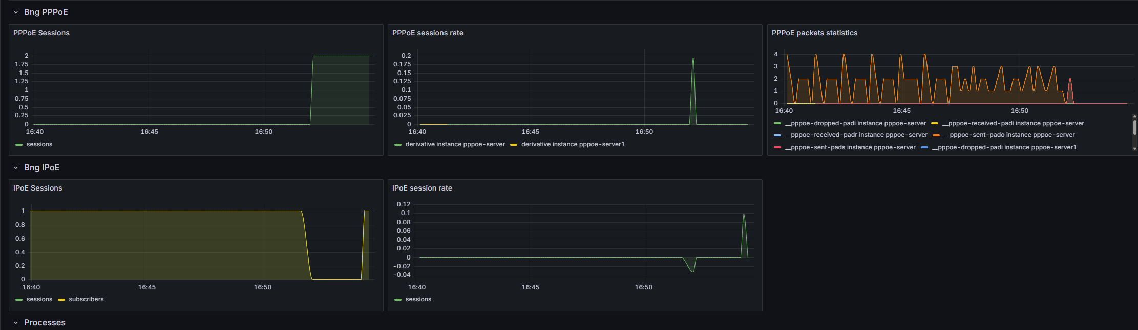
Lower in this BNG dashboard you can get a view on the number of current sessions.
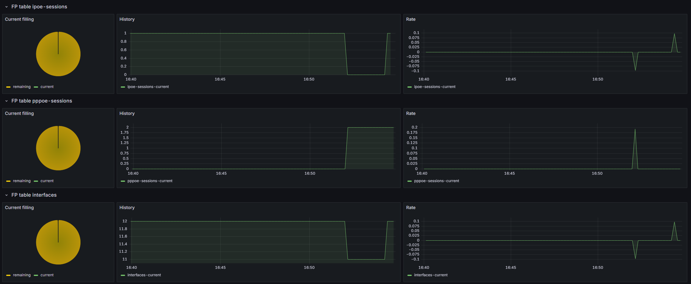
Now your BNG is also sending metrics on fast path & processes health that can be useful in future troubleshooting cases.
5.2. Logs
5.2.1. PPPoE logs
In PPP server, there are three different level of logs activation, the global log level for the whole ppp-server process, and two others for PPP & PPPoE sub-process. Regarding the whole server level, the default level is “error”, but you can choose to have more informations, which can be useful for troubleshooting purposes :
vBNG-CGNAT running config# / vrf main ppp-server instance pppoeService log-level
                          debug                Display all messages.
                          disable              Disable logging.
                          error                Display error message.  (Default level)
                          info                 Display error, warning and info message
                          warning              Display error and warning message.
Below an example of a normal PPP connections creation :
vBNG-CGNAT running config# show log
vBNG-CGNAT systemd-udevd[1462967]: Using default interface naming scheme 'v249'.
Same connection but with debug level :
vBNG-CGNAT running config# show log
vBNG-CGNAT main-ppp-server-pppoeService[1462488]: ppp0:cpe1: connect: ppp0 <--> pppoe(90:e2:ba:29:eb:54)
vBNG-CGNAT main-ppp-server-pppoeService[1462488]: ppp0:cpe1: cpe1: authentication succeeded
In order to obtain clearer informations on ipcp/ipv6cp or lcp negociations you can activate those specific logs :
vBNG-CGNAT running config# / vrf main ppp-server instance pppoeService ppp verbose true
vBNG-CGNAT running config# commit

vBNG-CGNAT main-ppp-server-pppoeService[1462488]: ppp0:cpe1: recv [LCP TermReq id=2]
vBNG-CGNAT main-ppp-server-pppoeService[1462488]: ppp0:cpe1: send [LCP TermAck id=2]
vBNG-CGNAT main-ppp-server-pppoeService[1462488]: ppp0:: disconnected
vBNG-CGNAT main-ppp-server-pppoeService[1462488]: to-CPEs:: send [LCP ConfReq id=fd <auth MSCHAP-v2> <mru 1492> <magic 08c53395>]
vBNG-CGNAT main-ppp-server-pppoeService[1462488]: to-CPEs:: recv [LCP ConfReq id=1 <mru 1492> <magic c3062c4b>]
vBNG-CGNAT main-ppp-server-pppoeService[1462488]: to-CPEs:: send [LCP ConfAck id=1]
vBNG-CGNAT main-ppp-server-pppoeService[1462488]: to-CPEs:: send [LCP ConfReq id=fd <auth MSCHAP-v2> <mru 1492> <magic 08c53395>]
vBNG-CGNAT main-ppp-server-pppoeService[1462488]: to-CPEs:: recv [LCP ConfAck id=fd <auth MSCHAP-v2> <mru 1492> <magic 08c53395>]
vBNG-CGNAT main-ppp-server-pppoeService[1462488]: to-CPEs:: send [MSCHAP-v2 Challenge id=1 <a65cec895cd623a176c82ad67da76a>]
vBNG-CGNAT main-ppp-server-pppoeService[1462488]: to-CPEs:: recv [MSCHAP-v2 Response id=1 <b8fc322abdf56a1d18edbe48777398f9>, <36ec1c4cef5c16a93c89e886903dcfb6b78917e1f7f1fdae>, F=0, name="cpe1"]
vBNG-CGNAT main-ppp-server-pppoeService[1462488]: ppp0:cpe1: connect: ppp0 <--> pppoe(90:e2:ba:29:eb:54)
vBNG-CGNAT main-ppp-server-pppoeService[1462488]: ppp0:cpe1: send [MSCHAP-v2 Success id=1 "S=03CFA1ED6F4F54FDAD92DE99E5F452ABE63E4685 M=Authentication succeeded"]
vBNG-CGNAT main-ppp-server-pppoeService[1462488]: ppp0:cpe1: cpe1: authentication succeeded
vBNG-CGNAT main-ppp-server-pppoeService[1462488]: ppp0:cpe1: send [IPCP ConfReq id=1 <addr 100.64.255.254>]
vBNG-CGNAT main-ppp-server-pppoeService[1462488]: ppp0:cpe1: recv [IPCP ConfReq id=1 <addr 0.0.0.0> <dns1 0.0.0.0> <dns2 0.0.0.0>]
vBNG-CGNAT main-ppp-server-pppoeService[1462488]: ppp0:cpe1: send [IPCP ConfRej id=1 <dns1 0.0.0.0> <dns2 0.0.0.0>]
vBNG-CGNAT main-ppp-server-pppoeService[1462488]: ppp0:cpe1: IPV6CP: discarding packet
vBNG-CGNAT main-ppp-server-pppoeService[1462488]: ppp0:cpe1: send [LCP ProtoRej id=255 <8057>]
vBNG-CGNAT main-ppp-server-pppoeService[1462488]: ppp0:cpe1: recv [IPCP ConfAck id=1 <addr 100.64.255.254>]
vBNG-CGNAT main-ppp-server-pppoeService[1462488]: ppp0:cpe1: recv [IPCP ConfReq id=2 <addr 0.0.0.0>]
vBNG-CGNAT main-ppp-server-pppoeService[1462488]: ppp0:cpe1: send [IPCP ConfNak id=2 <addr 100.64.0.4>]
vBNG-CGNAT main-ppp-server-pppoeService[1462488]: ppp0:cpe1: recv [IPCP ConfReq id=3 <addr 100.64.0.4>]
vBNG-CGNAT main-ppp-server-pppoeService[1462488]: ppp0:cpe1: send [IPCP ConfAck id=3]
Finally the same connections with pppoe logs activated :
vBNG-CGNAT running config# / vrf main ppp-server instance pppoeService pppoe verbose true
vBNG-CGNAT running config# commit

vBNG-CGNAT main-ppp-server-pppoeService[1462488]: to-CPEs: recv [PPPoE PADI 90:e2:ba:29:eb:54 => ff:ff:ff:ff:ff:ff sid=0000 <Service-Name > <Host-Uniq 37570100>]
vBNG-CGNAT main-ppp-server-pppoeService[1462488]: to-CPEs: send [PPPoE PADO 02:09:c0:25:4c:42 => 90:e2:ba:29:eb:54 sid=0000 <AC-Name accel-ppp> <Service-Name > <AC-Cookie a6c0829da075b6cddc00e2df3db72f7422a3089c9b7ba84e> <Host-Uniq 37570100>]
vBNG-CGNAT main-ppp-server-pppoeService[1462488]: to-CPEs: recv [PPPoE PADR 90:e2:ba:29:eb:54 => 02:09:c0:25:4c:42 sid=0000 <Service-Name > <Host-Uniq 37570100> <AC-Cookie a6c0829da075b6cddc00e2df3db72f7422a3089c9b7ba84e>]
vBNG-CGNAT main-ppp-server-pppoeService[1462488]: to-CPEs: send [PPPoE PADS 02:09:c0:25:4c:42 => 90:e2:ba:29:eb:54 sid=0140 <AC-Name accel-ppp> <Service-Name > <Host-Uniq 37570100>]
vBNG-CGNAT main-ppp-server-pppoeService[1462488]: to-CPEs:: send [LCP ConfReq id=57 <auth MSCHAP-v2> <mru 1492> <magic 2c3d49da>]
vBNG-CGNAT main-ppp-server-pppoeService[1462488]: to-CPEs:: recv [LCP ConfReq id=1 <mru 1492> <magic de5b8813>]
vBNG-CGNAT main-ppp-server-pppoeService[1462488]: to-CPEs:: send [LCP ConfAck id=1]
vBNG-CGNAT main-ppp-server-pppoeService[1462488]: to-CPEs:: send [LCP ConfReq id=57 <auth MSCHAP-v2> <mru 1492> <magic 2c3d49da>]
vBNG-CGNAT main-ppp-server-pppoeService[1462488]: to-CPEs:: recv [LCP ConfAck id=57 <auth MSCHAP-v2> <mru 1492> <magic 2c3d49da>]
vBNG-CGNAT main-ppp-server-pppoeService[1462488]: to-CPEs:: send [MSCHAP-v2 Challenge id=1 <a17387ce8ab74f197dec671bdef1fe15>]
vBNG-CGNAT main-ppp-server-pppoeService[1462488]: to-CPEs:: recv [MSCHAP-v2 Response id=1 <19931d666b5e59231dea46b1b77f932c>, <4555a5293f5cd0bb229b3850384466c44e3828ad4019e>, F=0, name="cpe1"]
vBNG-CGNAT main-ppp-server-pppoeService[1462488]: ppp0:cpe1: connect: ppp0 <--> pppoe(90:e2:ba:29:eb:54)
vBNG-CGNAT main-ppp-server-pppoeService[1462488]: ppp0:cpe1: send [MSCHAP-v2 Success id=1 "S=11EB2A1E2540AEFA79D6D9F15C65A2A1C26B6A8C M=Authentication succeeded"]
vBNG-CGNAT main-ppp-server-pppoeService[1462488]: ppp0:cpe1: cpe1: authentication succeeded
vBNG-CGNAT main-ppp-server-pppoeService[1462488]: ppp0:cpe1: send [IPCP ConfReq id=58 <addr 100.64.255.254>]
vBNG-CGNAT main-ppp-server-pppoeService[1462488]: ppp0:cpe1: recv [IPCP ConfReq id=1 <addr 0.0.0.0> <dns1 0.0.0.0> <dns2 0.0.0.0>]
vBNG-CGNAT main-ppp-server-pppoeService[1462488]: ppp0:cpe1: send [IPCP ConfRej id=1 <dns1 0.0.0.0> <dns2 0.0.0.0>]
vBNG-CGNAT main-ppp-server-pppoeService[1462488]: ppp0:cpe1: IPV6CP: discarding packet
vBNG-CGNAT main-ppp-server-pppoeService[1462488]: ppp0:cpe1: send [LCP ProtoRej id=89 <8057>]
vBNG-CGNAT main-ppp-server-pppoeService[1462488]: ppp0:cpe1: recv [IPCP ConfAck id=58 <addr 100.64.255.254>]
vBNG-CGNAT main-ppp-server-pppoeService[1462488]: ppp0:cpe1: recv [IPCP ConfReq id=2 <addr 0.0.0.0>]
vBNG-CGNAT main-ppp-server-pppoeService[1462488]: ppp0:cpe1: send [IPCP ConfNak id=2 <addr 100.64.0.5>]
vBNG-CGNAT main-ppp-server-pppoeService[1462488]: ppp0:cpe1: recv [IPCP ConfReq id=3 <addr 100.64.0.5>]
vBNG-CGNAT main-ppp-server-pppoeService[1462488]: ppp0:cpe1: send [IPCP ConfAck id=3]
5.2.2. IPoE logs
The default log level for IPoE is “error”, equally to PPP, which means no logs if everything’s ok. Anyway you can activate the debug logs to check how it behave in the background :
vBNG-CGNAT running config# / vrf main ipoe-server log-level debug
vBNG-CGNAT running config# commit

vBNG-CGNAT ipoe-server-main[1466958]: send [DHCPv4 Nak xid=2f7a8b87 chaddr=90:e2:ba:29:eb:54 <Message-Type Nak> <Server-ID 10.100.0.2> <Message Session dosn't exist>]
vBNG-CGNAT ipoe-server-main[1466958]: to-CPEs:: recv [DHCPv4 Discover xid=2a192c73 chaddr=90:e2:ba:29:eb:54 <Message-Type Discover> <Lease-Time 7200> <Request-List MTU,NTP,41,40,Host-Name,DNS,119,Domain-Name,Router,Time-Offset,Broadcast,Subnet>]
vBNG-CGNAT ipoe-server-main[1466958]: to-CPEs:to-CPEs_90:e2:ba:29:eb:54: to-CPEs_90:e2:ba:29:eb:54: authentication succeeded
vBNG-CGNAT ipoe-server-main[1466958]: to-CPEs:to-CPEs_90:e2:ba:29:eb:54: send [DHCPv4 Offer xid=2a192c73 yiaddr=10.100.0.11 chaddr=90:e2:ba:29:eb:54 <Message-Type Offer> <Server-ID 10.100.0.2> <Lease-Time 600> <T1 300> <T2 525> <Router 10.100.0.2> <Subnet 255.255.255.255>]
vBNG-CGNAT ipoe-server-main[1466958]: to-CPEs:to-CPEs_90:e2:ba:29:eb:54: recv [DHCPv4 Request xid=2a192c73 chaddr=90:e2:ba:29:eb:54 <Message-Type Request> <Server-ID 10.100.0.2> <Lease-Time 7200> <Request-IP 10.100.0.11> <Request-List MTU,NTP,41,40,Host-Name,DNS,119,Domain-Name,Router,Time-Offset,Broadcast,Subnet>]
vBNG-CGNAT ipoe-server-main[1466958]: to-CPEs:to-CPEs_90:e2:ba:29:eb:54: ipoe: session started hwaddr=90:e2:ba:29:eb:54
vBNG-CGNAT ipoe-server-main[1466958]: to-CPEs:to-CPEs_90:e2:ba:29:eb:54: send [DHCPv4 Ack xid=2a192c73 yiaddr=10.100.0.11 chaddr=90:e2:ba:29:eb:54 <Message-Type Ack> <Server-ID 10.100.0.2> <Lease-Time 600> <T1 300> <T2 525> <Router 10.100.0.2> <Subnet 255.255.255.255>]