1. Overview
This guide is aiming to show how to proceed to a typical BNG/CG-NAT scenario for common broadband ISP, using an IPv6 core network. We’ll deploy both PPPoE and IPoE tunnels, then finally handling IPv4 flows with a CG-NAT DS-Lite box (4in6). Thus BNG & CG-NAT will be managed by Virtual Service Router, they will be installed onto a proxmox hypervisor, avoiding deployment of multiple physicals appliances.
Of course this is only an example and you are totally free to use your own hypervisor (vmware/etc…).
To proceed we’ll see how to get best performances with proxmox by activating sr-iov functions, and binding our Virtual Service Router onto those VF.
Finally, we’ll learn how to activate QoS or traffic-limiting onto PPP sessions, then load-balance those PPP sessions onto three differents BNG.
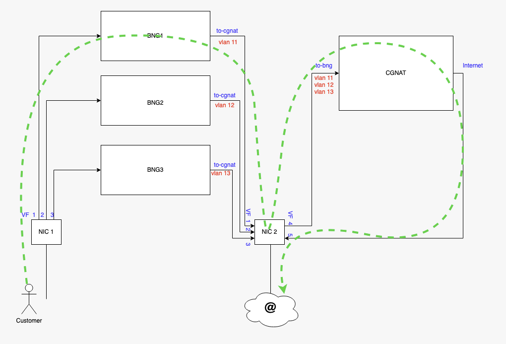
Consequently, we’ll build following topology, using two different physical NIC.
2. Install as a VM using Proxmox VE
This chapter explains how to start a Virtual Service Router VM using Proxmox VE and the .iso
file.
It expects that you already installed a Proxmox VE cluster, in which you are able to spawn VMs with network connected.
This document will guide you through the required steps needed to provision your Proxmox hypervisor.
It follows the following steps:
Prepare the host for high performance
Make the
.isofile available to Proxmox VECreate and configure a VM
Boot the VM using the
.isofileinstall Virtual Service Router on the virtual disk
Note
We recommend a proxmox hypervisor having at least 96GB of RAM with a physical CPU of 32 cores minimum
2.1. Finding SR-IOV capable interface on proxmox
We first need to find interfaces where we’ll activate SR-IOV on, so to proceed we need to log on the PVE server with an admin account (or root if it is the first boot of the server).
root@rome:~#  lspci -v | grep Ethernet
[...]
05:00.0 Ethernet controller: Intel Corporation 82599ES 10-Gigabit SFI/SFP+ Network Connection (rev 01)
            Subsystem: Intel Corporation Ethernet Server Adapter X520-2
05:00.1 Ethernet controller: Intel Corporation 82599ES 10-Gigabit SFI/SFP+ Network Connection (rev 01)
            Subsystem: Intel Corporation Ethernet Server Adapter X520-2
0b:00.0 Ethernet controller: Intel Corporation Ethernet Controller XL710 for 40GbE QSFP+ (rev 02)
            Subsystem: Intel Corporation Ethernet Converged Network Adapter XL710-Q2
0b:00.1 Ethernet controller: Intel Corporation Ethernet Controller XL710 for 40GbE QSFP+ (rev 02)
            Subsystem: Intel Corporation Ethernet Converged Network Adapter XL710-Q2
[...]
Next let’s confirm SR-IOV support. In our example we see that all the NICs are supported.
root@rome:~#  lspci -vvv | awk '/Ethernet/ {device=$0} /SR-IOV/ {print "***SR-IOV enabled***   "device}'


***SR-IOV enabled***        Subsystem: Intel Corporation Ethernet Server Adapter X520-2
***SR-IOV enabled***        Subsystem: Intel Corporation Ethernet Server Adapter X520-2
***SR-IOV enabled***        Subsystem: Intel Corporation Ethernet Converged Network Adapter XL710-Q2
***SR-IOV enabled***        Subsystem: Intel Corporation Ethernet Converged Network Adapter XL710-Q2
To see details, capabilities and required driver for a SR-IOV enabled devices the following command can be used :
lspci -v | grep -B 30 "SR-IOV"
To see details, capabilities and required driver for a certain NIC we can use the following command:
lspci -v | awk '/<PCI BUS>/','/^$/'
Note
We can also see the NUMA node the NIC is connected to.
root@rome:~#  lspci -v | awk '/05:00.0/','/^$/'

        05:00.0 Ethernet controller: Intel Corporation 82599ES 10-Gigabit SFI/SFP+ Network Connection (rev 01)
                Subsystem: Intel Corporation Ethernet Server Adapter X520-2
                Physical Slot: 1
                    Flags: bus master, fast devsel, latency 0, IRQ 16, NUMA node 0, IOMMU group 36
                    Memory at 39ffe080000 (64-bit, prefetchable) [size=512K]
                    I/O ports at 3020 [size=32]
                    Memory at 39ffe104000 (64-bit, prefetchable) [size=16K]
                Capabilities: [40] Power Management version 3
                Capabilities: [50] MSI: Enable- Count=1/1 Maskable+ 64bit+
                Capabilities: [70] MSI-X: Enable+ Count=64 Masked-
                Capabilities: [a0] Express Endpoint, MSI 00
                Capabilities: [100] Advanced Error Reporting
                Capabilities: [140] Device Serial Number 00-1b-21-ff-ff-74-59-04
                Capabilities: [150] Alternative Routing-ID Interpretation (ARI)
                Capabilities: [160] Single Root I/O Virtualization (SR-IOV)
                Kernel driver in use: ixgbe
                Kernel modules: ixgbe
This step only applies if you have multiple sockets on your hypervisor. Ensure the CPUs you pin to the VMs are from the same NUMA node as your NIC
cat /sys/bus/pci/devices/<PCI bus number>/numa_node
root@rome:~# cat /sys/bus/pci/devices/0000\:05\:00.0/numa_node
0
The output above is given as an example, it will differ on each server. Here we have the pci-id’s (05:00…) then the name of each NIC card embedded in the server.
05:00.0 Ethernet controller: Intel Corporation 82599ES 10-Gigabit SFI/SFP+ Network Connection (rev 01)
0b:00.0 Ethernet controller: Intel Corporation Ethernet Controller XL710 for 40GbE QSFP+ (rev 02)
As we need to match this pci-id to the name given by the kernel (eth1 or ens2f0 for example), you can match the “Device Serial Number” of this output, to the MAC address shown through an
root@rome:~# ip a
Or you can grep on system devices pci-id’s like below :
root@rome:~#  ls -l /sys/class/net | grep 0b:00
lrwxrwxrwx 1 root root        0 Nov 12 15:31 ens2f0 ->  [...] 0000:0b:00.0/net/ens2f0
lrwxrwxrwx 1 root root        0 Nov 12 15:31 ens2f1 -> [...] 0000:0b:00.1/net/ens2f1
2.2. Activate SR-IOV on proxmox
In order to be able to create VF (Virtual Function) on PF, we first need to enable this technology at boot.
Proceed with updating the grub configuration :
root@rome:~# vi /etc/default/grub
For an Intel processor, modify the 4th line :
GRUB_CMDLINE_LINUX_DEFAULT="quiet intel_iommu=on iommu=pt"
For an AMD processor, modify the 4th line :
GRUB_CMDLINE_LINUX_DEFAULT="quiet amd_iommu=on iommu=pt"
Once done, your file should look like this :

then update the grub configuration :
root@rome:~# update-grub
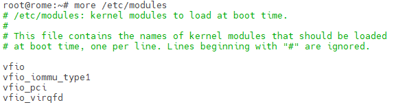
Modify the /etc/modules files to add kernel modules that are required at boot :
root@rome:~# vi /etc/modules
Once done, your file should look like this :
It is necessary to apply the modifications then restart the server :
root@rome:~# update-initramfs -u -k all
root@rome:~# reboot
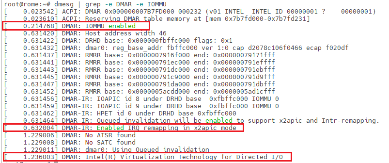
Once rebooted, you should be able to see the IOMMU activation :
root@rome:~# dmesg | grep -e DMAR -e IOMMU
2.3. Activate Hugepages mechanism on proxmox
In order to be able to get best performance in VSR VM, it is required to activate 1Gb hugepages, fast-path requires those 1Gb hugepages to work properly with good performances. They will be pre-allocated at fast-path starting, meaning that the RAM will be immediately reserved on you.
Proceed with updating the grub configuration :
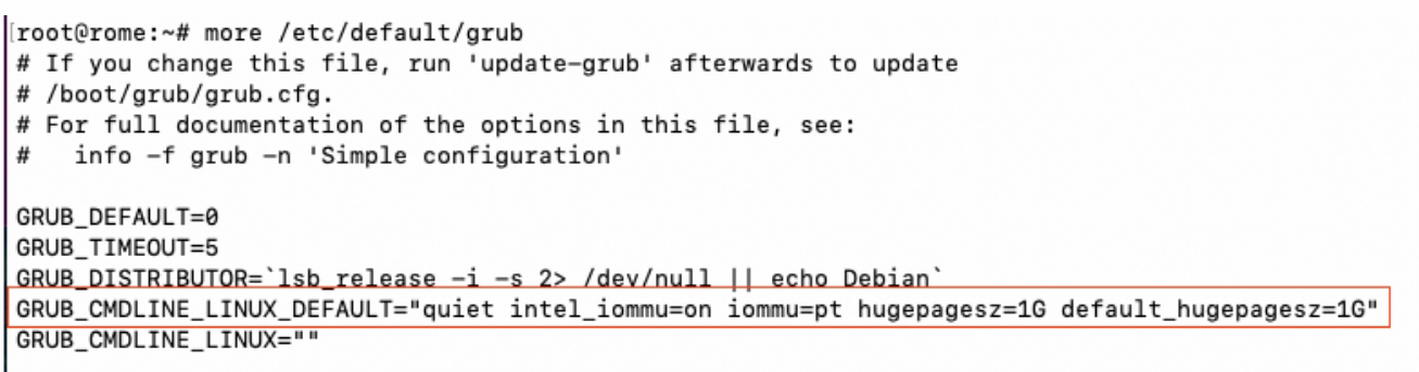
root@rome:~# vi /etc/default/grub
For Intel processor, modify the 4th line :
GRUB_CMDLINE_LINUX_DEFAULT="quiet intel_iommu=on iommu=pt hugepagesz=1G default_hugepagesz=1G"
For AMD processor, modify the 4th line :
GRUB_CMDLINE_LINUX_DEFAULT="quiet amd_iommu=on iommu=pt hugepagesz=1G default_hugepagesz=1G"
Grub configuration file should look like this :
then update the grub configuration and reboot the server :
root@rome:~# update-grub
root@rome:~# reboot
2.4. Set SR-IOV persistent
As a matter of example we’ll now create 3 VF on the first PF then 5 on the second PF, configure the VF so they receive a fixed mac address and activate the PF to be UP at each start, so our VM will be able to get network access as soon as they boot up. Without those actions, all VF will be vanished at each reboot.
To proceed we’ll create a fake service that will automatically create VF and set their mac adress at each boot. In order to create the required VF at boot time, edit the following file:
root@rome:~# vi /etc/systemd/system/sriov-NIC.service
Then populate it according to your needs and start the service:
[Unit]
Description=Script to enable SR-IOV on boot


[Service]
Type=oneshot
# Starting SR-IOV
ExecStart=/usr/bin/bash -c '/usr/bin/echo 3 > /sys/class/net/ens1f0/device/sriov_numvfs'
ExecStart=/usr/bin/bash -c '/usr/bin/echo 5 > /sys/class/net/ens2f0/device/sriov_numvfs'
# Setting static MAC for VFs
ExecStart=/usr/bin/bash -c '/usr/bin/ip link set ens1f0 vf 0 mac 02:fe:ed:00:01:00'
ExecStart=/usr/bin/bash -c '/usr/bin/ip link set ens1f0 vf 1 mac 02:fe:ed:00:01:01'
ExecStart=/usr/bin/bash -c '/usr/bin/ip link set ens1f0 vf 2 mac 02:fe:ed:00:01:02'
ExecStart=/usr/bin/bash -c '/usr/bin/ip link set ens2f0 vf 0 mac 02:fe:ed:00:02:00'
ExecStart=/usr/bin/bash -c '/usr/bin/ip link set ens2f0 vf 1 mac 02:fe:ed:00:02:01'
ExecStart=/usr/bin/bash -c '/usr/bin/ip link set ens2f0 vf 2 mac 02:fe:ed:00:02:02'
ExecStart=/usr/bin/bash -c '/usr/bin/ip link set ens2f0 vf 3 mac 02:fe:ed:00:02:03'
ExecStart=/usr/bin/bash -c '/usr/bin/ip link set ens2f0 vf 4 mac 02:fe:ed:00:02:04'
ExecStart=/usr/bin/bash -c '/usr/bin/ip link set dev ens1f0 vf 0 trust on'
ExecStart=/usr/bin/bash -c '/usr/bin/ip link set dev ens1f0 vf 1 trust on'
ExecStart=/usr/bin/bash -c '/usr/bin/ip link set dev ens1f0 vf 2 trust on'
ExecStart=/usr/bin/bash -c '/usr/bin/ip link set dev ens2f0 vf 0 trust on'
ExecStart=/usr/bin/bash -c '/usr/bin/ip link set dev ens2f0 vf 1 trust on'
ExecStart=/usr/bin/bash -c '/usr/bin/ip link set dev ens2f0 vf 2 trust on'
ExecStart=/usr/bin/bash -c '/usr/bin/ip link set dev ens2f0 vf 3 trust on'
ExecStart=/usr/bin/bash -c '/usr/bin/ip link set dev ens2f0 vf 4 trust on'


[Install]
WantedBy=multi-user.target
root@rome:~# systemctl enable sriov-NIC root@rome:~# systemctl start sriov-NIC
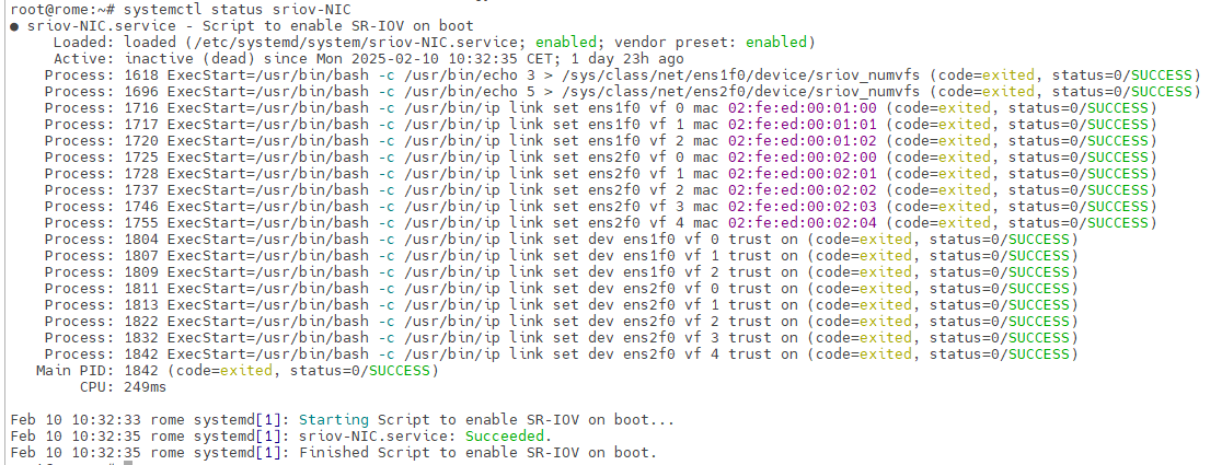
If the service starts without issues you should get such output :
root@rome:~# systemctl status sriov-NIC
2.4.1. Configure SR-IOV interfaces to be started automatically at boot time
Now that all of our VF are created, we can switch to proxmox web view.
In the “Server View”, click on your Proxmox Server name (rome in our case) > System > Network :
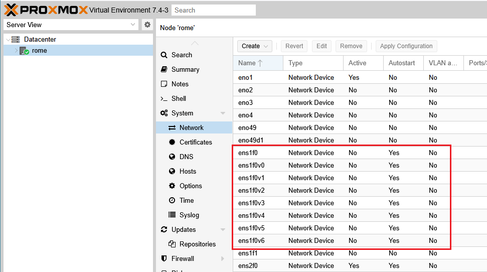
Here we can see the PF and all VF created, double click on each of them and check “Autostart”, then “ok“ :
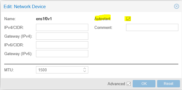
Consequently those PF/VF will be automatically set to status “UP” at each boot.
You can also verify or apply this setting by modifying the file : /etc/network/interfaces and adding : “auto ens1f0v0” before each statement “iface” :
auto ens1f0v0
iface ens1f0v0 inet manual
Once finished click “Apply Configuration”, the network service will restart to apply new configuration.
2.4.2. Mellanox caveats for MTU settings
Warning
Mellanox cards requires that MTU to be set physically at the hypervisor level to be correctly applied at VF level. It can imply MTU issues and consequently performances issues on your PPPoE or IPoE connection if the MTU is not correctly applied.
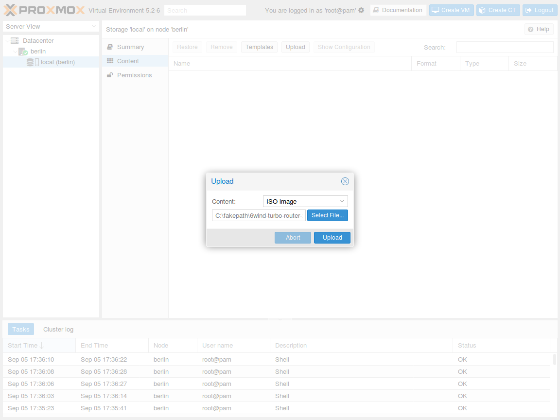
2.5. Upload the .iso file
Select the local storage of your node in the left pane and visualize its content:
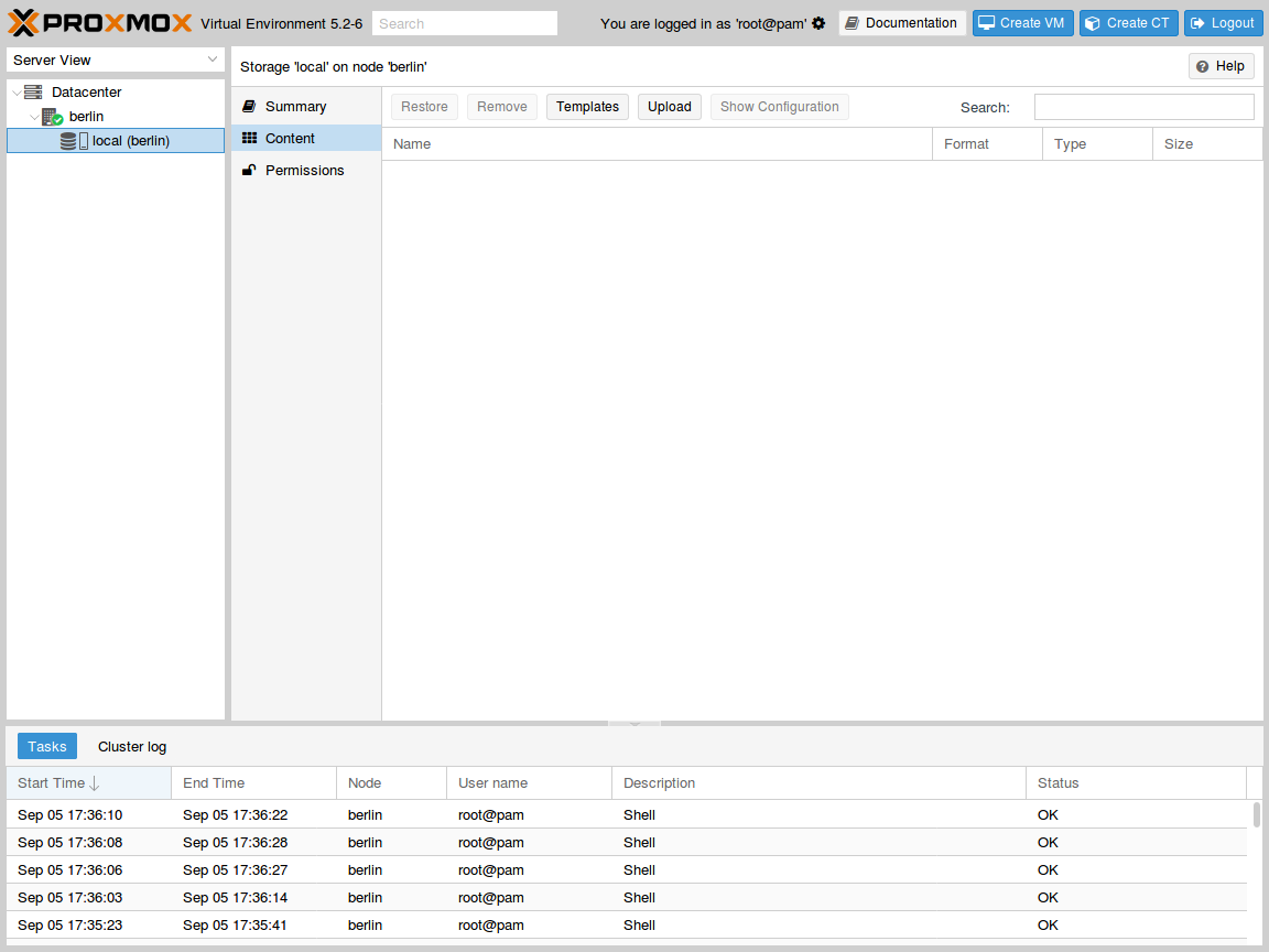
Press the Upload button. In the pop-up window, select ISO image as content
type and point to the Virtual Service Router .iso file on your local disk. Then press
Upload to send this file to your Proxmox VE node:
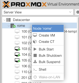
2.6. Create and boot the VM
Right clik on your proxmox server name, then press the Create VM button to launch the creation
wizard.
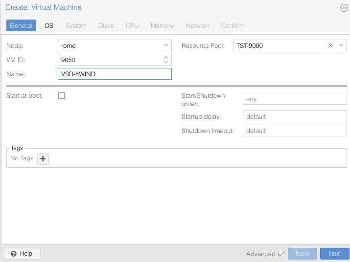
In General tab, check the node and the VM ID, and give a name to the
VM, optionally, if you previously configured a ressource pool, assign the VM to the desired one, once finished press Next:
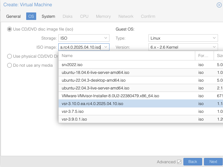
In OS tab, make sure to use the uploaded .iso file as CD/DVD and to specify
a Linux with 6.x-2.6 Kernel as Guest OS, then press Next:
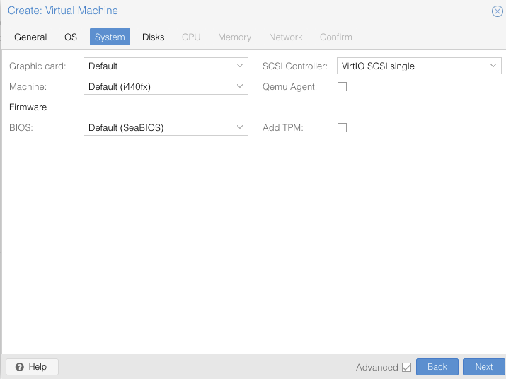
In System tab, keep the default settings.
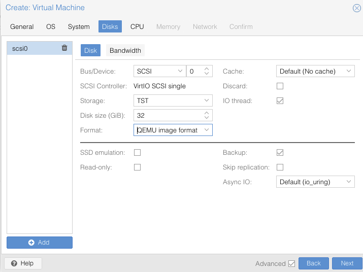
In Disks tab leave the Format setting to ‘QEMU image format qcow2’, Bus/device will stay as VirtIO SCSI storage, select the approriate storage you would have created before (TST here) and allocate at least 30GB, then press Next:
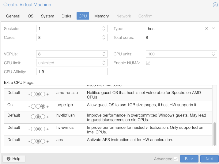
In CPU tab, allocate at least 8 cores on 1 socket and select host as CPU type, it is also the right time to specify the CPU affinity,
according to what we seen before, as well as the ” then
press Next:
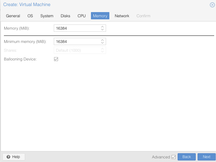
In Memory tab, allocate at least 16GB of RAM, then press Next:
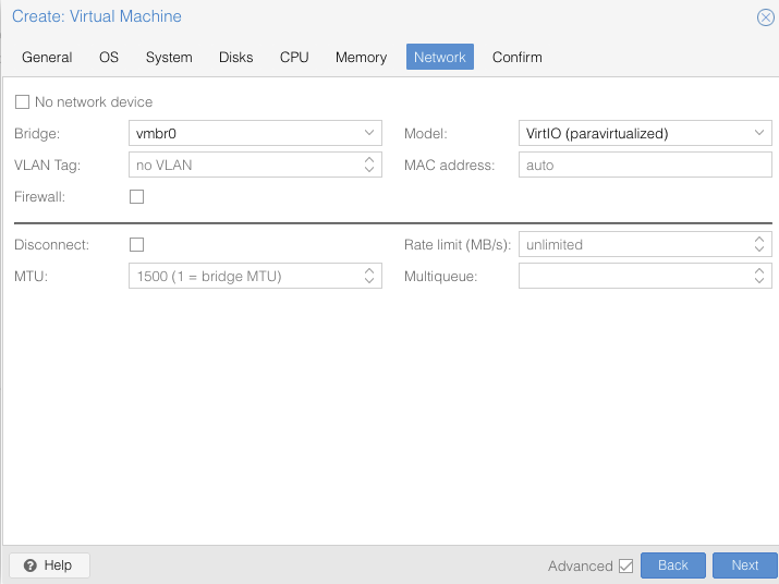
In Network tab, bind the virtual management interface to a host bridge in
order to have access to external network (usually vmbr0). Select VirtIO as model type, untick Firewall then press Next:
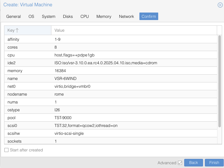
In Confirm tab, review your settings and press Finish to finalize the
creation and get back to the main dashboard:
The VM is now available in the left pane below your physical node. Once done you need to update your VM configuration. You can get your VM ID directly from GUI or through command :
qm list
Then update your VM configuration in the file {VM_ID}.conf as below :
root@rome:~# nano /etc/pve/qemu-server/9050.conf

Add “hugepages: 1024” and the flags “pdpe1gb” if not done during the VM creation as described above. Save the configuration then Stop & Start the VM for changes to take effect.
Now you can continue with the installation of your VM.
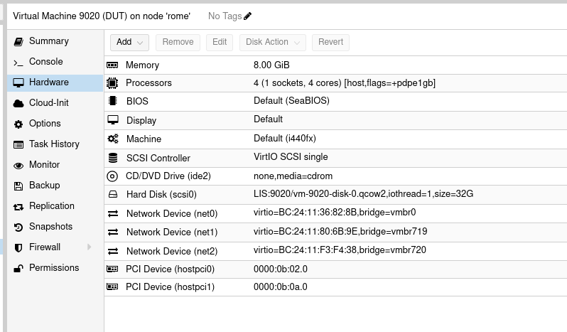
2.7. Set a VF to be used by a VM
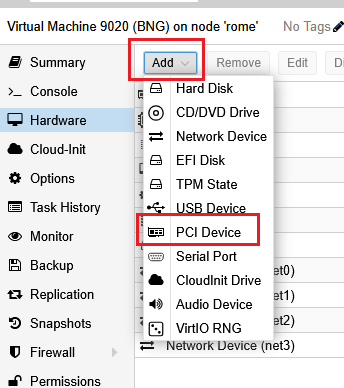
Now the VM is created, we still need to add our VF to it, so click on your VM name, then “Hardware”
Finally click “Add” then “PCI Device”
The window that open allow us to select one of the VF previously created, for example :
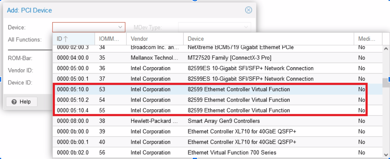
Into “Raw Device”, select one then validate, the VF is now added to the VM :

Warning
Be careful to verify “All functions” is not ticked, otherwise you’ll give all VF belonging to one physical card to your VM.
2.8. Focus on CPU Affinity for maximal performance
CPU affinity is crucial with VSR to get maximum performance, Proxmox allows you to fix CPU cores given to a VM.
Click on your VM name, then “Hardware”, then “edit” the “Processors” item :
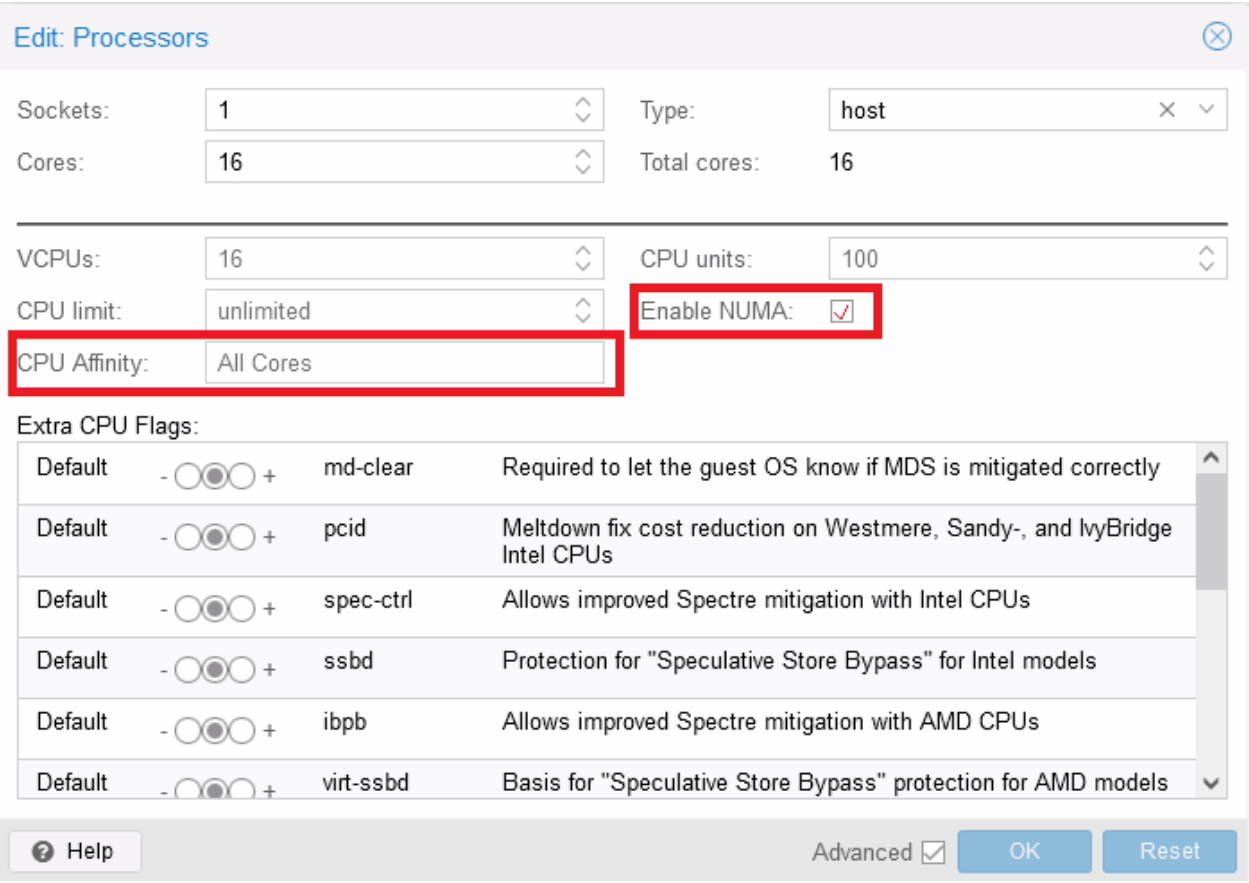
First, set “Type” to “host” to obtain best performances.
Here, as an example, you can specify to give the first four cores (0-3) of your host server to the VM, if you have multiple CPU on your server, be sure to enable “Enable NUMA”.
Most important thing is to give cores from the same NUMA node to the same VM and to ensure that the NICs are also connected to this same NUMA node. You can get your NUMA pattern by logging to the Proxmox server then issuing the following command :
root@rome:~# lscpu | grep NUMA
NUMA node(s):            4
NUMA node0 CPU(s):       0-7,32-39
NUMA node1 CPU(s):       8-15,40-47
NUMA node2 CPU(s):       16-23,48-55
NUMA node3 CPU(s):       24-31,56-63
For example, here, DO NOT give core 6-12 to one VM, as they will be spanned across two different physical nodes (0 and 1), hence reducing the performance. So you can assign CPUs 8-15,40-47.
CPU isolation: to get also better performance, you can isolate CPUs used by the system from those used by VMs and containers. Here is an example to allocate CPUs 0 to 3 to the system and keep CPUs 4 to 63 to machines and containers. And also you can exclude CPUs given to your VM “8-15,40-47” from those given to for other VMs and containers “4-7,16-39,48-63”.
systemctl set-property --runtime -- user.slice AllowedCPUs=0-3
systemctl set-property --runtime -- system.slice AllowedCPUs=0-3
systemctl set-property --runtime -- init.scope AllowedCPUs=0-3
systemctl set-property --runtime machine.slice AllowedCPUs=4-7,16-39,48-63
- you can also use this command to assign CPUs to your VMs:
- for the VM of BNG (replace 114 by your VM PID number).
taskset --cpu-list --all-tasks --pid 8-15,40-47 "$(< /run/qemu-server/114.pid)"
- for all other VMs (replace 100 by VMs PID numbers).
taskset --cpu-list --all-tasks --pid 4-7,16-39,48-63 "$(< /run/qemu-server/100.pid)"
2.9. VM requirements
Perform the creation of 4 VSR VM by repeating the above procedure 4 times. Your attributed VM settings should looks like this :
- VM 1 (BNG1) :
RAM : 16 GB
CPU Cores : 8 (4 physical cores so 8vCPUs)
VirtIO Interface : 2 (1 for management, 1 for radius connectivity)
VF : 2 (1st VF of 1st & 2nd PF so in current example : ens1f0v0 & ens2f0v0)
- VM 2 (BNG2) :
RAM : 16 GB
CPU Cores : 8 (4 physical cores so 8vCPUs)
VirtIO Interface : 2 (1 for management, 1 for radius connectivity)
VF : 2 (2nd VF of 1st & 2nd PF so in current example : ens1f0v1 & ens2f0v1)
- VM 3 (BNG3) :
RAM : 16 GB
CPU Cores : 8 (4 physical cores so 8vCPUs)
VirtIO Interface : 2 (1 for management, 1 for radius connectivity)
VF : 2 (3rd VF of 1st & 2nd PF so in current example : ens1f0v2 & ens2f0v2)
- VM 4 (CG-Nat):
RAM : 16 GB
CPU Cores : 8 (4 physical cores so 8vCPUs)
VirtIO Interface : 1 (1 for management)
VF : 2 (4th & 5th VF of 2nd PF so in current example : ens2f0v3 & ens2f0v4)
2.10. Install Virtual Service Router
Warning
Please carefully check the device associated to the disk you want to use, or
you could wipe the wrong drive in the next step. When following this
installation guide you have only one disk attached to the VM. Thus the
device name is sda. If you attach additional virtual disks, make sure to
choose the right device.
Warning
Please make sure that there is no other Virtual Service Router live CDROM or live USB inserted in this VM. Otherwise the system might fail to boot properly.
Press Start in the top right corner to actually start the VM.
Note
Please make sure to select this disk as boot device after installation. You can access boot menu by pressing ESC at startup in the VM console.
Once the VM has booted on the .iso file, select it in the left pane of the
main dashboard and press the >_ Console button to get access to the serial
console.
Log in as admin, password admin, and at the prompt, do:
vsr> cmd system-image install-on-disk sda
This command will install Virtual Service Router on /dev/sda. The relevant configuration
files will be copied to the local drive.
Reboot to finally boot Virtual Service Router from the virtual hard disk:
vsr> cmd reboot
3. Configure your first BNG
3.1. Configure management interface
First thing to do is to create a dedicated management interface, this will allow all your management traffic to be isolated from production one. To proceed further, we need to check wich interface is connected to the first VirtIO interface we created previously, the one connected to “vmbr0” into proxmox hypervisor.
Verify into Hardware of your VM settings, the mac address generated :
You’ll be able to verify the MAC is well there into your VSR CLI :
vsr> show state network-port
network-port pci-b0s16
    bus-addr 0000:00:10.0
    vendor "Intel Corporation"
    model "Ethernet Virtual Function 700 Series"
    mac-address 02:fe:ed:00:01:00
    interface ens16f0
    type physical
    ..
network-port pci-b0s18
    bus-addr 0000:00:12.0
    vendor "Red Hat, Inc."
    model "Virtio network device"
    mac-address bc:24:11:36:82:8b
    interface eth0
    type physical
    ..
network-port pci-b0s17
    bus-addr 0000:00:11.0
    vendor "Intel Corporation"
    model "Ethernet Virtual Function 700 Series"
    mac-address 02:fe:ed:00:02:00
    interface ens17
    type physical
    ..
network-port pci-b0s19
    bus-addr 0000:00:13.0
    vendor "Red Hat, Inc."
    model "Virtio network device"
    mac-address bc:24:11:80:6b:9e
    interface ntfp1
    type physical
Here, the first VirtIO interface is the one bound to pci-b0s18, consequently, let’s create a management interface with this one, into a dedicated management VRF (MGT), then we’ll activate our licence by using this newly created VRF. For simplicity reasons, we base our management interface onto a dhcp (that provide a DNS), of course if you have static addressing or even IPv6 then modify the configuration accordingly. We also take the benefit of this very beginning configuration to push an hostname on the VSR
vsr> edit running
vsr running config# / system hostname BNG1
vsr running config# commit
vsr running config#
BNG1 running config# / vrf MGT interface physical mgt0 port pci-b0s18
BNG1 running config# / vrf MGT interface physical mgt0 ipv4 dhcp
BNG1 running config# / vrf MGT ssh-server
BNG1 running config# commit
BNG1 running config# / system license online serial #### YOUR LICENCE #### BNG1 running config# / system license online vrf MGT BNG1 running config# commit BNG1 running config# exit BNG1> show licence show license Active perpetual license for Virtual Service Router License tokens 20 Current activations 1/20 Connected to license server (last contact 2025-03-25 08:08:39) Lease is valid until 2025-04-15 04:08:09 Serial number is #### YOUR LICENCE #### Computer ID is 2-------- License was activated online Support is valid until 2025-12-31 06:00:00 (standard mode)
Proceed for all other VM you installed. For more information you can see section Installing your license
3.2. Configure production interfaces
Now that our licence is activated, we can proceed to further configurations without issues. First we configure the interface intended for radius communication, our server is reachable at c, it will be facing our second virtio interface. We use such interface as radius communications doesn’t require high perfomances.
BNG1 running config# / vrf main interface physical to-radius description BNG1_to-Radius
BNG1 running config# / vrf main interface physical to-radius port pci-b0s19
BNG1 running config# / vrf main interface physical to-radius ipv4 address 172.20.1.11/24
BNG1 running config# commit
BNG1 running config#
BNG1 running config# cmd ping 172.20.1.1
PING 172.20.1.1 (172.20.1.1) 56(84) bytes of data.
64 bytes from 172.20.1.1: icmp_seq=1 ttl=64 time=0.620 ms
64 bytes from 172.20.1.1: icmp_seq=2 ttl=64 time=0.209 ms
Proceed equally for two other Virtual Service Router BNG with following ip addesses, BNG2 : 172.20.1.12/24, BNG3 : 172.20.1.13/24
We will now configure the interface that will face the customers (eth0), this one will be activated with IPv4 for PPP connections, and with IPv6 for IPoE as we’ll see later. As this interface require performance, we’ll use one of the VF we created and gave to the Virtual Service Router. This configuration has to be adapted according your use case.
BNG1 running config# / vrf main interface physical eth0 port pci-b0s16
BNG1 running config# / vrf main interface physical eth0 ipv4 address 172.16.0.1/24
We also configure interface heading to CG-NAT box, using the latest available VF, it will be useful later in this guide. Finally we route IPv4 packets to the cg-nat box
BNG1 running config# / vrf main interface physical to-cgnat port pci-b0s17
BNG1 running config# / vrf main interface vlan vcgnat ipv4 address 192.168.1.2/29
BNG1 running config# / vrf main interface vlan vcgnat vlan-id 10
BNG1 running config# / vrf main interface vlan vcgnat link-interface to-cgnat

BNG1 running config# / vrf main routing static ipv4-route 0.0.0.0/0 next-hop 192.168.1.2
Proceed equally for two other Virtual Service Router BNG :
BNG2 running config# / vrf main interface physical eth0 port pci-b0s16
BNG2 running config# / vrf main interface physical eth0 ipv4 address 172.17.0.1/24

BNG2 running config# / vrf main interface physical to-cgnat port pci-b0s17
BNG2 running config# / vrf main interface vlan vcgnat ipv4 address 192.168.2.2/29
BNG2 running config# / vrf main interface vlan vcgnat vlan-id 20
BNG2 running config# / vrf main interface vlan vcgnat link-interface to-cgnat

BNG2 running config# / vrf main routing static ipv4-route 0.0.0.0/0 next-hop 192.168.2.2
BNG3 running config# / vrf main interface physical eth0 port pci-b0s16 BNG3 running config# / vrf main interface physical eth0 ipv4 address 172.18.0.1/24 BNG3 running config# / vrf main interface physical to-cgnat port pci-b0s17 BNG3 running config# / vrf main interface vlan vcgnat ipv4 address 192.168.3.2/29 BNG3 running config# / vrf main interface vlan vcgnat vlan-id 30 BNG3 running config# / vrf main interface vlan vcgnat link-interface to-cgnat BNG3 running config# / vrf main routing static ipv4-route 0.0.0.0/0 next-hop 192.168.3.2
3.3. Configure QoS settings
3.3.1. HTB QoS Configuration
The following configuration has been used to define the 6WIND-qos-template used in our setup.
We’ll configure QoS based on a interface that can go up to 10Gb/s, we divide those 10G into two differents queues, first one for premium and other one for non-premium clients which will be the default queue for non authenticated or unmatched traffic. Premium clients will share 8G of reserved bandwith, with a maximum of 10G if available. Non-Premium will share 1G, with a maximum of 2G if available.
Note
Keep in mind that this QoS is acting only from BNG to CPE (so download from clients point of view), if you need to limit the upload, then you should use the rate-limiting mecanism (see below : 6WIND-limit).
3.3.2. Configure a base static scheduler
BNG1 running config# qos
BNG1 running qos# scheduler scheduler-1
BNG1 running scheduler scheduler-1# htb
BNG1 running htb# queue 1
BNG1 running queue1#! bandwidth 10G
BNG1 running queue1# ceiling 10G
BNG1 running queue1#! child-queue 2
BNG1 running queue1#! child-queue 3
BNG1 running queue1#! ..
BNG1 running htb# queue 2
BNG1 running queue2#! description "This is the static parent queue for premium subscribers queues"
BNG1 running queue2#! bandwidth 8G
BNG1 running queue2#! ceiling 10G
BNG1 running queue2#! ..
BNG1 running htb#! queue 3
BNG1 running queue3#! description "This is the static parent queue for non-premium subscribers queues"
BNG1 running queue3#! bandwidth 1G
BNG1 running queue3#! ceiling 2G
BNG1 running queue3#! ..
BNG1 running htb# default-queue 3
3.4. Radius configuration
The 6WIND BNG is configured with a PPP server function that supports the following Radius features which are key to our implementation and the establishment of the PPPoE session:
Authentication: Pointing to the RADIUS server for authenticating a given user.
Accounting: Sending user accounting information to gather how much time, packets, bytes, and other resources were consumed during the session to the Radius accounting server.
Change of authorization: The support of a change of authorization is restricted to some attributes, such as Traffic Limiting IPv4 and Reverse Path Filtering. Other attributes may be added in future versions.
IPv4 network information: PPP server accepts RADIUS IPv4 Framed-IP-Address and Framed-Route (RFC 2138).
Framed-Route: A static IPv4 route provided by Radius server to install in the Virtual Service Router routing table.
Framed-IP-Address: An IPv4 address provided by the Radius server to assign to the user’s PPP interface.
IPv6 network information: The PPP server accepts Radius IPv6 Framed-IPv6-Prefix, Framed-Interface-Id and Framed-IPv6-Route (RFC 3162):
Framed-Interface-Id: An IPv6 interface identifier to be configured on the user’s PPP interface.
Framed-IPv6-Prefix: An IPv6 prefix (and corresponding route) to be configured for the user. The prefix should have a 64-bit mask. For example 2001:db8:0:100::/64.
Framed-IPv6-Route: IPv6 routing information provided by Radius to be configured for the user in the Virtual Service Router routing table. It should be described as follows “PREFIX/MASK USER-IPv6-ADDRESS METRICS”. For example “2000:0:0:106::/64 2000::106:a00:20ff:fe99:a998 1”.
PREFIX/MASK is the destination prefix optionally followed by a mask.
USER-IPv6-ADDRESS is the gateway address, it should be the user’s IPv6 address. It can also be unspecified. For example, “2000:0:0:106::/64 :: 1”
Following this configuration you should configure your RADIUS server. In our setup, the RADIUS server is directly connected to the BNG router as previously mentioned, and we will list hereafter the content of the two configuration files that are required for the authentication process.
Note
For info, we have used FreeRadius version 3.0 installed in an Ubuntu 22.04, but you can use any product you are mostly familiar with.
In the clients.conf file, you need to configure the secret for the BNG-PPPoE router to allow for proper authentication (file found at /etc/freeradius/3.0/)
client BNG1 {
      ipaddr = 172.20.1.11
      secret = "5ecret123"
}
client BNG2 {
      ipaddr = 172.20.1.12
      secret = "5ecret123"
}
client BNG3 {
      ipaddr = 172.20.1.13
      secret = "5ecret123"
}
Further, you need to configure the 6WIND RADIUS dictionary file or Vendor-specific attributes in order to use them properly in our implementation. The following vendor-specific attribute definitions need to be created in the “dictionary.6WIND” file under the /usr/share/freeradius/ path:
#
# dictionary.6WIND
#
VENDOR          6WIND                    7336
BEGIN-VENDOR    6WIND
ATTRIBUTE       6WIND-AVPair             1       string
ATTRIBUTE       6WIND-limit              7       string
ATTRIBUTE       6WIND-iface-rpf          23      integer
ATTRIBUTE       6WIND-qos-template-name  24      string
ATTRIBUTE       6WIND-tr069-url          31      string
END-VENDOR      6WIND
Finally, add this line into “dictionary” file :
$INCLUDE dictionary.6wind
Once done modify your users file, where you’ll need to define parameters for the CPEs PPPoE sessions establishment (users file found at /etc/freeradius/3.0/users). Here is an example :
cpe1 Cleartext-Password := 'cpe1'
     Acct-Interim-Interval = 300,
     Service-Type = Framed-User,
     Framed-Protocol = PPP,
     Framed-Routing = Broadcast-Listen,
     Framed-Filter-Id = "std.ppp",
     Framed-Interface-Id = a00:20ff:fe99:a998,
     Framed-IP-Address = 100.64.10.1,
     Framed-IP-Netmask = 255.255.255.255,
     MS-Primary-DNS-Server = 1.1.1.1,
     Framed-IPv6-Prefix = "2000:0:0:106::/64",
     Framed-IPv6-Route = "2000:0:0:106::1/80 :: 1",
     6WIND-qos-template-name = premium-subscribers

cpe2 Cleartext-Password := 'cpe2'
     Acct-Interim-Interval = 300,
     Service-Type = Framed-User,
     Framed-Protocol = PPP,
     Framed-Routing = Broadcast-Listen,
     Framed-Filter-Id = "std.ppp",
     Framed-Interface-Id = a00:20ff:fe99:a999,
     Framed-IP-Address = 100.64.10.2,
     Framed-IP-Netmask = 255.255.255.255,
     MS-Primary-DNS-Server = 1.1.1.1,
     Framed-IPv6-Prefix = "2000:0:0:107::/64",
     Framed-IPv6-Route = "2000:0:0:107::1/80 :: 1",
     6WIND-qos-template-name = premium-subscribers,
     6WIND-tr069-url = "https://15.143.211.172:1234",
     6WIND-limit += "in= 55 1 10 1 mbps",
     6WIND-limit += "out= 55 1 10 1 mbps"
3.5. Configure fast-path settings
For this critical configuration, we will include both VF we passed to the VM, as they will handle customers flows, moreover PPP & IPoE servers require fast-path interfaces to work properly.
BNG1 running config# / system fast-path enabled true
BNG1 running config#! / system fast-path port pci-b0s16
BNG1 running config# / system fast-path port pci-b0s17
In order to be able to get 10000 sessions, it is mandatory to update some Fast-Path parameters : As each PPP session is done on a dedicated PPP interface hosted by the Fast-Path, increasing the maximum number of interfaces and PPPoE sessions accepted by the FP is mandatory :
BNG1 running config# / system fast-path limits fp-max-if 10300
BNG1 running config# / system fast-path limits pppoe-max-channel 10300
BNG1 running config# / system fast-path limits ip4-max-addr 10300
BNG1 running config# / system fast-path limits ip6-max-addr 10300
In most cases a QoS profile will be applied to each session. We take the example of 2 different typology of customers (premium / non premium customers) each with 2 classes of traffic which will need to be shaped at different bandwidth. In this case you need:
Scheduler is in charge of applying the QoS profile, there will be 1 scheduler per subscriber plus some margin in case of maximum sessions reached is a bit higher than 10000, it can happen if sessions are still negotiated while we reach effectively 10000.
Policies determine which action must be taken depending on the Policies selector match. Here we have two possible policies per user, including some margin : 21000
Queues correspond to the queues where each customer class of traffic will be sent. 2 queues are created in above example, adding margin once again : 50000
BNG1 running config# / system fast-path limits qos-max-schedulers 10300
BNG1 running config# / system fast-path limits qos-max-policies 21000
BNG1 running config# / system fast-path limits qos-max-queues 50000
3.6. Configure PPP server
We will define a maximum of 10000 sessions that will be given an IP in the 172.16.0.0/16 pool, we also limit the amount of sessions accepted per second to 500. Finally we set the dns server that will be sent to CPE
Let’s bind the PPP server to interface eth0 :
BNG1 running config# / vrf main ppp-server instance pppoe-server pppoe enabled true
BNG1 running config# / vrf main ppp-server instance pppoe-server ppp ipcp require
BNG1 running config# / vrf main ppp-server instance pppoe-server ip-pool default-local-ip 172.16.255.254
BNG1 running config# / vrf main ppp-server instance pppoe-server ip-pool pool pppoe peer-pool 172.16.0.0/16
BNG1 running config# / vrf main ppp-server instance pppoe-server pppoe ip-pool pppoe
BNG1 running config# / vrf main ppp-server instance pppoe-server pppoe interface eth0
BNG1 running config# / vrf main ppp-server instance pppoe-server dns server 8.8.8.8
BNG1 running config# / vrf main ppp-server instance pppoe-server dns server 9.9.9.9
Now we configure the authentication to be bound to a RADIUS, this one will be directly connected through interface to-radius previously configured.
BNG1 running config# / vrf main ppp-server instance pppoe-server auth radius enabled true
BNG1 running config# / vrf main ppp-server instance pppoe-server auth radius default-local-ip 172.16.255.254
BNG1 running config# / vrf main ppp-server instance pppoe-server auth radius server address 172.20.1.1 auth-port 1812 acct-port 1813 secret 5ecret123
BNG1 running config# / vrf main ppp-server instance pppoe-server auth radius nas
BNG1 running config# / vrf main ppp-server instance pppoe-server auth radius nas ip-address 172.20.1.11
BNG1 running config# / vrf main ppp-server instance pppoe-server auth radius nas identifier 172.20.1.11
BNG1 running config# / vrf main ppp-server instance pppoe-server auth radius change-of-authorization-server
BNG1 running config# / vrf main ppp-server instance pppoe-server auth radius change-of-authorization-server ip-address 172.20.1.1
BNG1 running config# / vrf main ppp-server instance pppoe-server auth radius change-of-authorization-server secret 5ecret123
Note
We set the accounting interval to 300s which is a good balance between getting frequent accounting, and the load is will induce to PPP process. The jitter is also configured at 180s, meaning the effective accounting packets will be sent every 300s +/- 180s, avoiding pikes in radius traffic. Those values can be modified according to your needs.
BNG1 running config# / vrf main ppp-server instance pppoe-server auth radius accounting interim-interval 300
BNG1 running config# / vrf main ppp-server instance pppoe-server auth radius accounting interim-jitter 180
BNG1 running config# / vrf main ppp-server instance pppoe-server auth radius accounting session-id-in-authentication true
We also need to take care of load-balancing sessions between all BNG instances, the following pado-delay setting is used to increase the time taken to send PADO (Offers) to the customer, allowing that another BNG instance will answer quicker, hence handling the new load. Once the last BNG reach its first threshold, then the load is back to the first BNG as it answer quicker than two others. Adapt the below delays (in ms) according to your needs :
BNG1 running config# / vrf main ppp-server instance pppoe-server pppoe pado-delay session-count 1000 delay 100
BNG1 running config# / vrf main ppp-server instance pppoe-server pppoe pado-delay session-count 3000 delay 300
BNG1 running config# / vrf main ppp-server instance pppoe-server pppoe pado-delay session-count 5000 delay 500
BNG1 running config# / vrf main ppp-server instance pppoe-server pppoe pado-delay session-count 7000 delay 700
Second instance :
BNG2 running config# / vrf main ppp-server instance pppoe-server pppoe pado-delay session-count 1000 delay 200
BNG2 running config# / vrf main ppp-server instance pppoe-server pppoe pado-delay session-count 3000 delay 400
BNG2 running config# / vrf main ppp-server instance pppoe-server pppoe pado-delay session-count 5000 delay 600
BNG2 running config# / vrf main ppp-server instance pppoe-server pppoe pado-delay session-count 7000 delay 800
Third instance :
BNG3 running config# / vrf main ppp-server instance pppoe-server pppoe pado-delay session-count 1000 delay 300
BNG3 running config# / vrf main ppp-server instance pppoe-server pppoe pado-delay session-count 3000 delay 500
BNG3 running config# / vrf main ppp-server instance pppoe-server pppoe pado-delay session-count 5000 delay 700
BNG3 running config# / vrf main ppp-server instance pppoe-server pppoe pado-delay session-count 7000 delay 900
Optionally, you can also configure KPIs.
BNG1> edit running
BNG1 running config# / vrf mgt kpi telegraf metrics monitored-interface vrf main name eth0
BNG1 running config# / vrf mgt kpi telegraf metrics monitored-interface vrf main name to-radius
BNG1 running config# / vrf mgt kpi telegraf metrics monitored-interface vrf main name to-cgnat
BNG1 running config# / vrf mgt kpi telegraf metrics template all
BNG1 running config# / vrf mgt kpi telegraf influxdb-output url http://<server-ip>:8086 database telegraf
BNG1 running config# commit
For the other instances, we change the IP pool and radius identifier.
For example:
BNG2 running config# / vrf main ppp-server instance pppoe-server ip-pool default-local-ip 172.17.255.254
BNG2 running config#! / vrf main ppp-server instance pppoe-server ip-pool pool pppoe peer-pool 172.17.0.0/18
BNG2 running auth# / vrf main ppp-server instance pppoe-server auth radius nas ip-address 172.20.1.12
BNG2 running auth# / vrf main ppp-server instance pppoe-server auth radius nas identifier 172.20.1.12
BNG3 running config# / vrf main ppp-server instance pppoe-server ip-pool default-local-ip 172.18.255.254
BNG3 running config#! / vrf main ppp-server instance pppoe-server ip-pool pool pppoe peer-pool 172.18.0.0/16
BNG3 running auth# / vrf main ppp-server instance pppoe-server auth radius nas ip-address 172.20.1.13
BNG3 running auth# / vrf main ppp-server instance pppoe-server auth radius nas identifier 172.20.1.13
3.6.1. Limiting accepted sessions per second
Once done we’ll limit the amount of sessions accepted per second, as it can lead to overload the PPP server. It applies PER instance of BNG.
A Number of “starting” session increasing constantly is a sign of overload of the control plane daemon. This setting has direct impact on the “starting” counter, see below.
The right number can differ according to your BNG capacities (number of CPU given to control plane), here we’ll take the minimum case of 4 vCPU given to control plane. We recommend setting this value between 300 & 600.
BNG1 running config# / vrf main ppp-server instance pppoe-server max-starting 500
BNG1 running instance pppoe-server# show ppp-server statistics instance pppoe-server
     Sessions counters
      active    : 6153
  --> starting  : 321 <--
      finishing : 0

     PPPoE counters
      active        : 6474
      starting      : 0
      PADI received : 53394
      PADI dropped  : 0
      PADO sent     : 14119
      PADR received : 73298
      PADS sent     : 6474
See also
See the User’s Guide for more information regarding:
3.6.2. Add the base-scheduler to the PPP server interface
BNG1 running config# vrf main interface physical eth0 qos egress scheduler scheduler-1
3.6.3. Configure the Templates locally
The template will deployed within the PPP server configuration, this one will splitted into two different queues:
premium-subscribers
non-premium-subscribers
Then each queues will be splitted into two dynamic queues, each one will look for an internal firewall tag to be effectively used. In below examples, we reserve at least 15M for VoIP traffic, and 950M for standard traffic, this traffic will be measured according the global queue we definied previously : queue 2. This one define a maximum of 10G traffic, meaning that with below configuration we can have a maximum of 10 premium clients using their session at 100% (10 x ~1G) with standard traffic.
BNG1 running config# vrf main ppp-server instance pppoe-server qos
BNG1 running qos# template premium-subscribers scheduler-interface eth0
BNG1 running qos# template premium-subscribers queue prem static-parent 2
BNG1 running qos# template premium-subscribers queue prem bandwidth 1G
BNG1 running qos# template premium-subscribers queue prem ceiling 1G
BNG1 running qos# template premium-subscribers queue prem-voip dynamic-parent prem
BNG1 running qos# template premium-subscribers queue prem-voip bandwidth 15M
BNG1 running qos# template premium-subscribers queue prem-voip ceiling 50M
BNG1 running qos# template premium-subscribers queue prem-voip mark 0x1
BNG1 running qos# template premium-subscribers queue prem-data dynamic-parent prem
BNG1 running qos# template premium-subscribers queue prem-data bandwidth 950M
BNG1 running qos# template premium-subscribers queue prem-data ceiling 950M
BNG1 running qos# template premium-subscribers queue prem-data mark 0x0

BNG1 running qos# template non-premium-subscribers scheduler-interface eth0
BNG1 running qos# template non-premium-subscribers queue non-prem static-parent 3
BNG1 running qos# template non-premium-subscribers queue non-prem bandwidth 50M
BNG1 running qos# template non-premium-subscribers queue non-prem ceiling 100M
BNG1 running qos# template non-premium-subscribers queue non-prem-voip dynamic-parent non-prem
BNG1 running qos# template non-premium-subscribers queue non-prem-voip bandwidth 1M
BNG1 running qos# template non-premium-subscribers queue non-prem-voip ceiling 2M
BNG1 running qos# template non-premium-subscribers queue non-prem-voip mark 0x1
BNG1 running qos# template non-premium-subscribers queue non-prem-data dynamic-parent non-prem
BNG1 running qos# template non-premium-subscribers queue non-prem-data bandwidth 49M
BNG1 running qos# template non-premium-subscribers queue non-prem-data ceiling 98M
BNG1 running qos# template non-premium-subscribers queue non-prem-data mark 0x0

BNG1 running qos# default-template non-premium-subscribers
Once the configuration is in place, the RADIUS setup of a user should include its QoS template name, for instance, for a premium user the attribute is: (/etc/freeradius/3.0/users)
6WIND-qos-template-name = premium-subscribers
If no attribute can be retrieved from the RADIUS server, the default template is used (non-premium-subscribers).
3.6.4. Configure QoS marking
In this implementation, the VOIP traffic is marked with 0x1. The other traffic has the mark 0x0 (equivalent to no mark). The marking can be done using the IP Packet Filtering context.
Below we’ll see an example of traffic marking using the standard Virtual Service Router firewall. Keep in mind that this mark is purely local to the Virtual Service Router, as a metadata to the packets, and won’t be replicated once the packet has left the system.
First lets assume you have a standard SIP VOIP traffic on TCP 5060/5061 ports, coming from your customers without any DSCP marking. We need to mark packets as soon as they arrive on the interface, so they’ll be handled correctly. Consequently we’ll use the PREROUTING target in the mangle table which is the dedicated table to alter packets with such marking.
BNG1 running qos# / vrf main firewall ipv4 mangle prerouting
BNG1 running qos# rule 1 protocol tcp destination port-range 5060-5061 action mark 0x1
BNG1 running qos# commit
The mark 0x1 will be catched by the QoS mechanism we saw below and packets will be sent to the right queue according your template.
3.6.5. Protecting control plane packet
By default the control plane traffic is not processed differently than the dataplane traffic in the QoS. There is no security to protect control packets from being dropped at QoS enqueue. To protect them you can configure a queue dedicated to control plane packets with a guarantee bandwidth.
BNG1 running config# / qos classifier cp-traffic match-control-plane-traffic true
BNG1 running config# / qos scheduler scheduler-1 htb queue 5 bandwidth 1M
BNG1 running config# / qos scheduler scheduler-1 htb queue 5 classifier cp-traffic
Now you are sure that a bandwidth of 1 Mbps is reserved for control plane packets only.
3.6.6. PPPoE health checks
You can verify if the ppp server is up and running, and the configuration applied with the following command.
BNG1> show state vrf main ppp-server instance pppoe-server
instance pppoe-server
    enabled true
    prevent-restart-on-change false
    single-session disable
    max-sessions 10000
    max-starting 0
    log-level error
    ppp
        verbose false
 [...]
There’s also filtering possibilities, as, for example, adding the sessions-state, or asking directly a list of current sessions :
BNG1> show state vrf main ppp-server instance pppoe-server session-state
session-state ppp0
    username cpe1
    peer-ip 172.18.0.1
    local-ip 172.18.255.254
    type pppoe
    state active
    uptime 18:17:33
    rx-bytes 828
    tx-bytes 54

BNG1> show ppp-server session instance pppoe-server
interface username mac address       ip address status uptime   l3vrf vlans
========= ======== ===========       ========== ====== ======   ===== =====
ppp0      cpe1     90:e2:ba:29:eb:54 172.18.0.1 active 18:17:00
With the ‘show ppp-server’ you can obtain details on a session, particularly on address/prefix attributed, as well as the QoS or l3vrf applied.
BNG1> show ppp-server session instance pppoe-server details
*************************************
Interface: ppp0
User name: cpe1
MAC address: 90:e2:ba:29:eb:54
IPv4 address: 172.18.0.1
IPv6 address: none
Status: active
Up since: 18:16:31
l3vrf: none
Vlans: none
PPPoE session ID: 128
IPv6 delegated prefix: none
Inbound interface: eth0
Acct-Session-Id: 92ffc8e9caceef02
QoS template: non-premium-subscribers
Incoming rate limit: none
Outgoing rate limit: none
*************************************
3.7. Configure IPoE server
The 6WIND BNG is configured with a IPoE server function that supports the following DHCP features that are key to our implementation and the establishment of the IPoE session:
IPoE DHCP relay: When a DHCP client requests an IP address, it transmits a DHCPDISCOVER message. This message is a broadcast that targets all devices on the local subnet. Since routers inherently prevent broadcasts from reaching other subnets, the DHCP server must implicitly reside in the same local Ethernet segment, unless an intermediate delivery mechanism is in place. In many large networks, it is neither possible nor efficient to have a DHCP server on every Ethernet segment. Therefore it would be preferred to have centralized DHCP servers serving multiple sites. More often, these servers are not on the same Layer 2 domain as the clients they serve. This is where the DHCP relay agent comes into play, acting as an intermediary to forward client broadcast requests to one or more servers, and reciprocally retransmit server responses back to clients.
3.7.1. IPv4 options
Agent Information: GIADDR and DHCP option 82: The DHCP relay agent writes the value of relay-address into the DHCP GIADDR header of the end device DHCP request and retransmits the packet to the designated servers from the relay-agent-address source IP address. If another relay agent subsequently receives this packet, the source IP address of the packet is changed, but the GIADDR header remains the same. Known as “Relay Agent Information”, DHCP option 82, specified in RFC 3046, can provide additional context on the relay agent. If the DHCP request does not yet contain the GIADDR and option 82, the relay agent can optionally insert this information if either the remote-id or link-selection parameters are set.
The
remote-idglobal option sets sub-option 2 of option 82. It globally identifies remote end devices through a specific string.On the other hand, the
link-selectionoption refers to sub-option 5 of option 82 which is detailed in RFC 3527. Its purpose is to provide the DHCP servers with the IP address of the IPoE server interface, especially when this address differs from the GIADDR. The DHCP GIADDR header and DHCP option 82 can help DHCP servers determine the appropriate pool for IP address allocation. They are also frequently used to log the IP address locations.The
trusted-circuitparameter determines whether the relay agent should forward DHCP requests that already transited via a relay agent, either with a valid GIADDR header or with DHCP option 82 By default, the value is false, meaning these requests are considered as untrusted. This prevents the relay agent from forwarding DHCP requests containing authentic or fake information about the agent. If the parameter is set to true, incoming DHCP requests are accepted and forwarded, provided their GIADDR header does not spoof the local GIADDR value.DHCP Client’s identification of the Router and Relay Agent: The DHCP option 54, referred to as the “Server Identifier”, is set by the DHCP server to include its own IP address in the responses it sends. A standard relay agent transmits this option unaltered. Subsequently, following the DHCP lease’s initialization, the DHCP client interacts directly with the DHCP server, bypassing the DHCP relay agent. However, since the IPoE relay is designed to forward all DHCP interactions to preserve IPoE sessions, it swaps the “Server Identifier” in option 54 with its own IP address. Inversely, the relay agent replaces the “Server Identifier” value in client requests with the real server IP. The router setting determines the IP address that the relay should present to clients via DHCP option 54. If this setting is undefined, the system automatically defaults to a local IP address.
The DHCP option 3, known as the “Router” option, provides the end device with a default gateway. The router setting determines the value set in DHCP option 3. Any pre-existing option 3 value from the DHCP server is substituted with this router setting. If left unspecified, the relay agent retains the original value of option 3.
3.7.2. IPv6 options
When a DHCPv6 client sends a request (SOLICIT), the DHCPv6 relay can extract information (such as MAC address, interface, etc.) to generate a dynamic username and password. It can also realiser the insertion of identification options (Option 18, Option 37, Option 79, etc…)
Option 18 (
Interface-ID): Allows the relay to inform the DHCPv6 server on which interface the client request has been received. It can include port index, VLAN and the client’s DUID. May be useful for identifying the physical access point of the client, for authentication or policy application.Option 37 (
Remote-ID): provides a unique identifier for the client across the network. It can include MAC address, ingress port, VLAN, DUID and enterprise number (See IANA Numbers database). Used for tracking the origin of the request and for centralized authentication by the DHCPv6 server or AAA backend.Option 79 (
Client Link-Layer Address): Can be used to include the client’s MAC address in relayed messages. Optional, depending on equipment and identification needs.
Now our PPPoE connection is up and running, we want to address the specific usecase of customer having IPv6 only connection, as they need a 6to4 NAT.
3.7.3. Configuration
An IPoE server will be configured in the main VRF, we will use the internal DHCPv6 embedded within the IPoE server.
Configure IPoE server in main VRF for 10000 sessions and a dhcp ip pool fc00:0:1::1/64.
BNG1> edit running
BNG1 running config# / vrf main interface physical eth0 ipv6 address fc00:0:1::1/64
BNG1 running config# / vrf main ipoe-server enabled true
BNG1 running config# / vrf main ipoe-server limits max-session 10000
BNG1 running config# / vrf main ipoe-server dhcpv6-server ip6-pool poolCPE
BNG1 running config# / vrf main ipoe-server dhcpv6-server ip6-pools-setup
BNG1 running config# / vrf main ipoe-server dhcpv6-server ip6-pools-setup pool poolCPE
BNG1 running config# / vrf main ipoe-server dhcpv6-server ip6-pools-setup pool poolCPE prefix fc00:0:1::/48
BNG1 running config# / vrf main ipoe-server dhcpv6-server ip6-pools-setup pool poolCPE prefix-len 64
BNG1 running config# / vrf main ipoe-server dhcpv6-server ip6-dns server 8::8
BNG1 running config# / vrf main ipoe-server dhcpv6-server ip6-dns server 9::9
We set the lease to be valid between 3000 & 3600s, the server ID is mandatory, it will be based on a DUID-Link Layer format :
BNG1 running config# / vrf main ipoe-server dhcpv6-server lease pref-lifetime 3000
BNG1 running config# / vrf main ipoe-server dhcpv6-server lease valid-lifetime 3600
BNG1 running config# / vrf main ipoe-server dhcpv6-server server-id 1:0:0:1
Finally we also set a delegated-prefix pool for host behind the CPE.
BNG1 running config# / vrf main ipoe-server dhcpv6-server ip6-pools-setup prefix-delegation cpePD
BNG1 running config# / vrf main ipoe-server dhcpv6-server ip6-pools-setup prefix-delegation cpePD prefix 2000:0:1:100::/60
BNG1 running config# / vrf main ipoe-server dhcpv6-server ip6-pools-setup prefix-delegation cpePD prefix-len 64
BNG1 running config# / vrf main ipoe-server dhcpv6-server ipv6-prefix-delegation cpePD
We’ll also bind the IPoE server to interface eth0 :
BNG1 running config# / vrf main ipoe-server dhcpv6-server interface eth0
Now we configure the authentication to be bound to a RADIUS, this one will be directly connected through interface to-radius previously configured.
Regarding authentication we’ll use following criterias (username/password will be identicals) :
Interface where the IPoE sessions (DHCP packets) are coming from
Client MAC address
Note
Depending on your environment you are free to use following options :
{server_interface} : Interface’s name receiving DHCP packet.
{agent_remote_id} : Agent remote ID (option 82 sub-option 2 for DHCPv4, option 37 for DHCPv6).
{circuit_id} : Agent circuit ID (option 82 sub-option 1).
{client_hwaddress}: Peer hardware (MAC) address.
{client_tagX_vlan_id}/{client_tagX_qinq_id} : VLAN or QINQ id in decimal, where X is the VLAN or QINQ order in the Ethernet frame. It starts at 1 which is the order of the outer tag.
BNG1 running config# / vrf main ipoe-server auth
BNG1 running ipoe-server# username {server_interface}_{client_hwaddress}
BNG1 running ipoe-server# password {server_interface}_{client_hwaddress}
BNG1 running ipoe-server# radius server address 172.20.1.1 auth-port 1812 acct-port 1813 secret 5ecret123
BNG1 running ipoe-server# radius nas ip-address 172.20.1.11
BNG1 running ipoe-server# radius nas identifier 172.20.1.11
BNG1 running ipoe-server# radius change-of-authorization-server ip-address 172.20.1.1
BNG1 running ipoe-server# radius change-of-authorization-server secret 5ecret123
BNG1 running ipoe-server# radius accounting interim-interval 300
BNG1 running ipoe-server# radius accounting interim-jitter 180
BNG1 running ipoe-server# radius accounting session-id-in-authentication true
- For the other instances, use the same configuration but change the DHCPv6 pool, eth0 IP address and finally radius identifier.
For example:
BNG2> edit running
BNG2 running config# / vrf main interface physical eth0 ipv6 address fc00:0:2::1/64
BNG2 running config# / vrf main ipoe-server dhcpv6-server ip6-pools-setup pool poolCPE prefix fc00:0:2::/48
BNG2 running config# / vrf main ipoe-server dhcpv6-server ip6-pools-setup pool poolCPE prefix-len 64
BNG2 running config# / vrf main ipoe-server dhcpv6-server server-id 1:0:0:2
BNG2 running config# / vrf main ipoe-server auth radius nas ip-address 172.20.1.12
BNG2 running config# / vrf main ipoe-server auth radius nas identifier 172.20.1.12
BNG2 running config# / vrf main ipoe-server dhcpv6-server ip6-pools-setup prefix-delegation cpePD prefix 2000:0:2:100::/60
BNG3> edit running
BNG3 running config# / vrf main interface physical eth0 ipv6 address fc00:0:3::1/64
BNG3 running config# / vrf main ipoe-server dhcpv6-server ip6-pools-setup pool poolCPE prefix fc00:0:3::/48
BNG3 running config# / vrf main ipoe-server dhcpv6-server ip6-pools-setup pool poolCPE prefix-len 64
BNG3 running config# / vrf main ipoe-server dhcpv6-server server-id 1:0:0:3
BNG3 running config# / vrf main ipoe-server auth radius nas ip-address 172.20.1.13
BNG3 running config# / vrf main ipoe-server auth radius nas identifier 172.20.1.13
BNG3 running config# / vrf main ipoe-server dhcpv6-server ip6-pools-setup prefix-delegation cpePD prefix 2000:0:3:100::/60
3.7.4. Configuring Radius
Firstly check the mandatory radius config here Configuring Radius section.
Then you’ll find below a Freeradius configuration example for an IPoE account, eth0 stands for {server_interface} then _ then {client_hwaddress}
We also put this client into the “premium-subscribers” queue, and set a traffic limit to 55M, with a maximum of 60M in upload (from CPE point of view)
eth0_02:00:00:00:01:16 Cleartext-Password := 'eth0_02:00:00:00:01:16'
Acct-Interim-Interval = 60,
6WIND-qos-template-name = premium-subscribers,
6WIND-tr069-url = "https://15.143.211.172:1234",
6WIND-limit += "in= 55 1 10 1 mbps",


eth0_02:00:00:00:01:17 Cleartext-Password := 'eth0_02:00:00:00:01:17'
Acct-Interim-Interval = 60,
See also
See the User’s Guide for more information regarding:
3.7.5. Configure the Templates locally
We use the same template defined for PPP.
BNG1 running config# / vrf main ipoe-server qos
BNG1 running qos# template premium-subscribers scheduler-interface eth0
BNG1 running qos# template premium-subscribers queue prem static-parent 2
BNG1 running qos# template premium-subscribers queue prem bandwidth 1G
BNG1 running qos# template premium-subscribers queue prem ceiling 1G
BNG1 running qos# template premium-subscribers queue prem-voip dynamic-parent prem
BNG1 running qos# template premium-subscribers queue prem-voip bandwidth 15M
BNG1 running qos# template premium-subscribers queue prem-voip ceiling 50M
BNG1 running qos# template premium-subscribers queue prem-voip mark 0x1
BNG1 running qos# template premium-subscribers queue prem-data dynamic-parent prem
BNG1 running qos# template premium-subscribers queue prem-data bandwidth 950M
BNG1 running qos# template premium-subscribers queue prem-data ceiling 950M
BNG1 running qos# template premium-subscribers queue prem-data mark 0x0

BNG1 running qos# template non-premium-subscribers scheduler-interface eth0
BNG1 running qos# template non-premium-subscribers queue non-prem static-parent 3
BNG1 running qos# template non-premium-subscribers queue non-prem bandwidth 50M
BNG1 running qos# template non-premium-subscribers queue non-prem ceiling 100M
BNG1 running qos# template non-premium-subscribers queue non-prem-voip dynamic-parent non-prem
BNG1 running qos# template non-premium-subscribers queue non-prem-voip bandwidth 1M
BNG1 running qos# template non-premium-subscribers queue non-prem-voip ceiling 2M
BNG1 running qos# template non-premium-subscribers queue non-prem-voip mark 0x1
BNG1 running qos# template non-premium-subscribers queue non-prem-data dynamic-parent non-prem
BNG1 running qos# template non-premium-subscribers queue non-prem-data bandwidth 49M
BNG1 running qos# template non-premium-subscribers queue non-prem-data ceiling 98M
BNG1 running qos# template non-premium-subscribers queue non-prem-data mark 0x0

BNG1 running qos# default-template non-premium-subscribers
3.7.6. IPoE health checks
You can verify if the ipoe server is up and running, and the configuration applied with the following command.
BNG1> show state vrf main ipoe-server

ipoe-server
    enabled true
    prevent-restart-on-change false
    log-level debug
    aggregated-sessions 0
    limits
        max-session 10000
        ..
    auth
        username {server_interface}_{client_hwaddress}
        password {server_interface}_{client_hwaddress}
        radius
            timeout 5
            max-failure 3
            enabled true
            server address 172.20.1.1 auth-port 1812 acct-port 1813 secret 5ecret123
            nas
                ipv4-address 172.20.1.11
                identifier 172.20.1.11
                ..
            change-of-authorization-server
                ip-address 172.20.1.1
                port 3799
                secret 5ecret123
                ..
            accounting
                interim-interval 300
                interim-jitter 180
                session-id-in-authentication true
                allow-unreachable enabled false max-retry 3 timeout 60
                ..
            ..
        ..
    dhcpv6-server
        ip6-pool poolCPE
        ip6-pools-setup
            pool poolCPE
                prefix fc00:0:1::/48
                prefix-len 64
                used 1
                total 256
                ..
            prefix-delegation cpePD
                prefix 2000:0:1:100::/60
                prefix-len 64
                used 1
                total 64
                ..
            ..
        interface eth0
            access-mode L2
            ..
        ip6-dns
            server 8::8
            server 9::9
            ..
        lease
            pref-lifetime 3000
            valid-lifetime 3600
            ..
        server-id 1:0:0:1
        ipv6-prefix-delegation cpePD
        ..
    statistics
        sessions 1
        subscribers 1
        ..
    ..
There’s also filtering possibilities, as, for example, adding the sessions-state, or asking directly a list of current sessions :
BNG1> show ipoe-server session
interface username mac address       ip address                    status uptime   l3vrf vlans server
========= ======== ===========       ==========                    ====== ======   ===== ===== ======
ipoe0     eth0     90:e2:ba:29:eb:54 fc00:0:1:0:dced:2ff:feef:49a7 active 00:00:41
With the ‘show ipoe-server’ you can obtain details on a session, particularly on address/prefix attributed, as well as the QoS or l3vrf applied.
BNG1> show ipoe-server session details
*******************************************
Interface: ipoe0
User name: eth0
MAC address: 90:e2:ba:29:eb:54
IP address: fc00:0:1:0:dced:2ff:feef:49a7
Status: active
Up since: 00:00:44
l3vrf: none
Vlans: none
Server: none
IPv6 delegated prefix: 2000:0:1:100::/64
Inbound interface: eth0
Acct-Session-Id: 92ffc8e9cacee724
Circuit ID: none
Remote ID: none
QoS template: non-premium-subscribers
Incoming rate limit: none
Outgoing rate limit: none
*******************************************
4. Configure CG-Nat
Now all our BNG are configured we’ll update the configuration to be usable in a ds-lite scenario We’ll use an ipip interface that will be the ds-lite tunnel endpoint onto the cg-nat box, then we’ll update the BNG configuration so it can send the tunnel endpoint information (fqdn) to CPE’s through dhcp option 64. As we use this fqdn to obtain information on CPE, it means they need to reach a DNS server that can help them to resolve it.
4.1. Configure management interface
As we did at the begining of this guide, we add a management interface into a dedicated vrf.
vsr> edit running
vsr running config# / system hostname CGNAT
vsr running config# commit
CGNAT running config# / vrf MGT interface physical mgt0
CGNAT running config# ipv4 dhcp
CGNAT running config# pci-b0s18
CGNAT running config#
CGNAT running config# / vrf MGT ssh-server enable true
CGNAT running config# commit
4.2. Configure production interfaces
Here we set IPv6 addresses on three vlans interfaces that will be bound to the interface facing the BNG. Those interface must be into fast-path in order to get a working cg-nat.
CGNAT running config# / vrf main interface physical to-bng port pci-b0s16
CGNAT running config# / vrf main interface vlan vbng1 ipv4 address 192.168.1.1/29
CGNAT running config# / vrf main interface vlan vbng1 ipv6 address fd00:100::1/120
CGNAT running config# / vrf main interface vlan vbng1 vlan-id 10
CGNAT running config# / vrf main interface vlan vbng1 link-interface to-bng

CGNAT running config# / vrf main interface vlan vbng2 ipv4 address 192.168.2.1/29
CGNAT running config# / vrf main interface vlan vbng2 ipv6 address fd00:200::1/120
CGNAT running config# / vrf main interface vlan vbng2 vlan-id 20
CGNAT running config# / vrf main interface vlan vbng2 link-interface to-bng

CGNAT running config# / vrf main interface vlan vbng3 ipv4 address 192.168.3.1/29
CGNAT running config# / vrf main interface vlan vbng3 ipv6 address fd00:300::1/120
CGNAT running config# / vrf main interface vlan vbng3 vlan-id 30
CGNAT running config# / vrf main interface vlan vbng3 link-interface to-bng
Those address will be used to build ds-lite tunnel as we’ll see below.
In order to obtain IPv6 connectivity between CGNAT & BNG’s, we must set the IPv6 on our three BNG box interfaces
BNG1 running config# / vrf main interface vlan vcgnat ipv6 address fd00:100::2/120

BNG2 running config# / vrf main interface vlan vcgnat ipv6 address fd00:200::2/120

BNG3 running config# / vrf main interface vlan vcgnat ipv6 address fd00:300::2/120
As we are talking about internet NATing device, we configure an interface heading to internet. Here we add a static IPv4, and a static route to handle IPv4 traffic, but you can use a bgp peering for example to have a greater granularity on your routing policy.
CGNAT running config# / vrf main interface physical to-internet
CGNAT running config# port pci-b0s17
CGNAT running config# ipv4 address A.B.C.D/28
4.3. Configure fast-path settings
For this critical configuration, we include both VF used for PPPoE & IPoE traffic and also facing to internet, as they will handle customers flows, moreover cg-nat require fast-path interfaces to work properly.
CGNAT running config# / system fast-path enabled true
CGNAT running config#! / system fast-path port pci-b0s16
CGNAT running config# / system fast-path port pci-b0s17
It is necessary to increase the maximum block-size and/or translation-ips to match what pool we will allow to users. As a matter of example, below we configure the limits to 6 public IP shared by all users, then each users will be given one IP, and 512 ports for its traffic.
CGNAT running config# / system fast-path limits cg-nat max-block-size 512
CGNAT running config# / system fast-path limits cg-nat max-block-translation-ips 6
4.4. Configure DS-Lite interfaces
Finally we use IPIP interfaces, they are intended to encapsulate IP packets, so here we gonna encapsulate all IPv4 traffic into IPv6 packets, then the IPv6 will be removed and natted according cg-nat configuration we’ll see later
We create three differents interfaces, one for each BNG, the local address is the one of vlans created before, and the remote address is basically every CPE. The important statement is the ‘ds-lite-aftr true’ that enable the ds-lite feature.
CGNAT running config# / vrf main interface ipip aftr1
CGNAT running config# local fd00:100::1
CGNAT running config# remote ::
CGNAT running config# link-interface vbng1
CGNAT running config# ds-lite-aftr true

CGNAT running config# / vrf main interface ipip aftr2
CGNAT running config# local fd00:200::1
CGNAT running config# remote ::
CGNAT running config# link-interface vbng2
CGNAT running config# ds-lite-aftr true

CGNAT running config# / vrf main interface ipip aftr3
CGNAT running config# local fd00:300::1
CGNAT running config# remote ::
CGNAT running config# link-interface vbng3
CGNAT running config# ds-lite-aftr true
Consequently we must handle the routing backwards to customer, as we dedicated a pool for each CPE, things are quite easy here :
CGNAT running config# / vrf main routing static ipv6-route fc00:0:1::/48 next-hop fd00:100::2
CGNAT running config# / vrf main routing static ipv6-route fc00:0:2::/48 next-hop fd00:200::2
CGNAT running config# / vrf main routing static ipv6-route fc00:0:3::/48 next-hop fd00:300::2
In order - on each BNG - to allow them to send the DS-Lite tunnel information, need to add an important configuration line into IPoE server :
BNG1 running config# / vrf main ipoe-server dhcpv6-server aftr-name bng1-aftr.mycompany.com

BNG2 running config# / vrf main ipoe-server dhcpv6-server aftr-name bng2-aftr.mycompany.com

BNG3 running config# / vrf main ipoe-server dhcpv6-server aftr-name bng3-aftr.mycompany.com
Note
We do not cover in this guide the DNS server installation, as well as the network reachability of it. Anyway, you must ensure to have record entries as :
bng1-aftr       IN      AAAA    fd00:100::1
bng2-aftr       IN      AAAA    fd00:200::1
bng3-aftr       IN      AAAA    fd00:300::1
4.5. CG-NAT basic rules
Below you’ll find the definition of a pool containing 6 IPv4 addresses, they will be shared accross all clients, each of them will receive 512 ports dynamically allowed..
Note
Here we see the matching between the fast-path limits we modified earlier, /29 allows 6 IP to be used and the block-size we attribute to each user is 512 ports.
CGNAT running config# / vrf main cg-nat pool mypool address A.B.C.D/29
CGNAT running config# / vrf main cg-nat pool mypool allocation-mode dynamic-block block-size 512
CGNAT running config# / vrf main cg-nat rule 1 dynamic-snat44 translate-to pool-name mypool
Regarding IPoE traffic, the source address of the IPv4 packets can be anything, meaning we accept every host that can be behind a CPE behind IPoE traffic. We also add the outbound interface as a matching criteria.
CGNAT running config# / vrf main cg-nat rule 1 dynamic-snat44 match source ipv4-address 0.0.0.0/0
CGNAT running config# / vrf main cg-nat rule 1 dynamic-snat44 match outbound-interface to-internet
Now we also specify the softwire address for rule 1, which means the IP attributed to the CPE by the BNG. As we saw, depending on the BNG, attributed IP’s will be within a dedicated /48 pool, so here we specify our three possible /48 where the cg-nat process will be able to extract and handle packets.
CGNAT running config# / vrf main cg-nat rule 1 dynamic-snat44 match ds-lite softwire-address fc00:0:1::/48
CGNAT running config# / vrf main cg-nat rule 1 dynamic-snat44 match ds-lite softwire-address fc00:0:2::/48
CGNAT running config# / vrf main cg-nat rule 1 dynamic-snat44 match ds-lite softwire-address fc00:0:3::/48
Finally we do an equivalent configuration for packets coming from PPP customer :
CGNAT running config# / vrf main cg-nat rule 2 dynamic-snat44 match source ipv4-address 172.16.0.0/16
CGNAT running config# / vrf main cg-nat rule 2 dynamic-snat44 match source ipv4-address 172.17.0.0/16
CGNAT running config# / vrf main cg-nat rule 2 dynamic-snat44 match source ipv4-address 172.18.0.0/16
CGNAT running config# / vrf main cg-nat rule 2 dynamic-snat44 match outbound-interface to-internet
CGNAT running config# / vrf main cg-nat rule 2 dynamic-snat44 translate-to pool-name mypool
4.6. CG-NAT health checks
We can verify how many users are catched into each rules :
CGNAT> show cg-nat user-count
rule 1:
3

CGNAT> show cg-nat user
rule 1:
172.16.0.2
        8 conntracks
        1/1 tcp blocks, 0/1 udp blocks, 0/1 icmp blocks, 0/1 gre blocks
        1 no port errors, 0 no block errors, 0 no public ip errors, 0 full public ip errors
172.17.0.230
        8 conntracks
        1/1 tcp blocks, 0/1 udp blocks, 0/1 icmp blocks, 0/1 gre blocks
        1 no port errors, 0 no block errors, 0 no public ip errors, 0 full public ip errors
172.18.0.55
        8 conntracks
        1/1 tcp blocks, 0/1 udp blocks, 0/1 icmp blocks, 0/1 gre blocks
        1 no port errors, 0 no block errors, 0 no public ip errors, 0 full public ip errors

CGNAT> show cg-nat pool-address pool-name mypool
A.B.C.D
        1/8064 tcp blocks, 1/8064 udp blocks, 1/8064 icmp blocks, 1/8064 gre blocks
A.B.C.E
        2/8064 tcp blocks, 2/8064 udp blocks, 2/8064 icmp blocks, 2/8064 gre blocks

CGNAT> show cg-nat pool-usage pool-name mypool
tcp block usage: 3/16128 (0.02%)
udp block usage: 3/16128 (0.02%)
icmp block usage: 3/16128 (0.02%)
gre block usage: 3/16128 (0.02%)

CGNAT> show cg-nat conntracks user-address 192.168.0.2
rule 1:
CONN:
        state: time_wait alg:none inactive_since:53s timeout:120s
        origin: tcp 192.168.0.2:42389 -> 10.100.0.1:8000
        reply : tcp 10.100.0.1:8000 -> 10.205.3.4:1030
        NAT source: 192.168.0.2:42389 -> 10.205.3.4:1030
        di:egress iface:eth0
CONN:
        state: time_wait alg:none inactive_since:53s timeout:120s
        origin: tcp 192.168.0.2:48733 -> 10.100.0.1:8000
        reply : tcp 10.100.0.1:8000 -> 10.205.3.4:1028
        NAT source: 192.168.0.2:48733 -> 10.205.3.4:1028
        di:egress iface:eth0
CONN:
        state: time_wait alg:none inactive_since:53s timeout:120s
        origin: tcp 192.168.0.2:36269 -> 10.100.0.1:8000
        reply : tcp 10.100.0.1:8000 -> 10.205.3.4:1026
        NAT source: 192.168.0.2:36269 -> 10.205.3.4:1026
        di:egress iface:eth0
CONN:
        state: time_wait alg:none inactive_since:53s timeout:120s
        origin: tcp 192.168.0.2:42957 -> 10.100.0.1:8000
        reply : tcp 10.100.0.1:8000 -> 10.205.3.4:1024
        NAT source: 192.168.0.2:42957 -> 10.205.3.4:1024
        di:egress iface:eth0
5. KPI & Logs handling
6WIND KPI monitoring provides the ability to monitor and export Virtual Service Router KPIs. For this, the metrics should first be collected with the internal KPI daemon to the be sent via the Telegraf agent to external monitoring tools via its output plugins.
See also
You can get detailed informations in the official documentation : 6WIND KPI
5.1. KPI collection
You first need to install grafana dashboard on a monitoring server, be sure it can be reached through the management as we’ll enable KPI into mgt vrf we created previously.
See also
All useful informations can be easily found on our GitHub
Reach a CLI session on your monitoring server then launch the automated configuration (below commands are launched on an ubuntu-based distribution, adapt according your case) :
$ apt-get update
$ apt-get install docker-compose python3-requests docker.io
$ git clone https://github.com/6WIND/supervision-grafana.git
$ cd supervision-grafana
$ ./start tools/confs/vsr-3.10.yaml
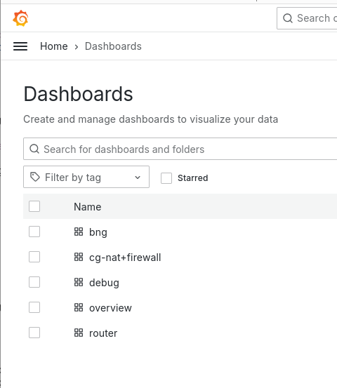
Once the script is finished, you should be able to reach your monitoring server on port 3000 : http://monitoring.mycompany.com:3000
Now we’ll set up the KPI daemon (in vrf mgt) to collect metrics and statistics on relevant interfaces (eth0 & to-radius) :
BNG1 running config# / vrf mgt kpi telegraf metrics template all
BNG1 running config# / vrf mgt kpi telegraf metrics monitored-interface vrf main name eth0
BNG1 running config# / vrf mgt kpi telegraf metrics monitored-interface vrf main name to-radius
Now we add the monitoring server where telegraf will send the datas :
BNG1 running config# / vrf mgt kpi telegraf influxdb-output url http://monitoring.mycompany.com:8086
BNG1 running config# / vrf mgt kpi telegraf influxdb-output url http://monitoring.mycompany.com:8086 database telegraf
Here we used influxdb as a database, but you can use various methods like :
BNG1 running config# / vrf mgt kpi telegraf ?
  amazon-cloudwatch-output      Amazon CloudWatch connection options.
  elasticsearch-output          Elasticsearch connection options.
  graphite-output               Graphite connection options.
  influxdb-output               InfluxDB v1.x connection options.
  influxdbv2-output             InfluxDB v2 connection options.
  kafka-output                  Kafka connection options.
  prometheus-client-output      Prometheus client connection options.
Allow few times for data to be collected, then you should be able to reach the dashboard, then the bng dashboard. In this dashboard you can view few informations as the CPU load on linux & fast path, the number of current sessions (PPP or IPoE, traffic currently handled by monitored interfaces. :
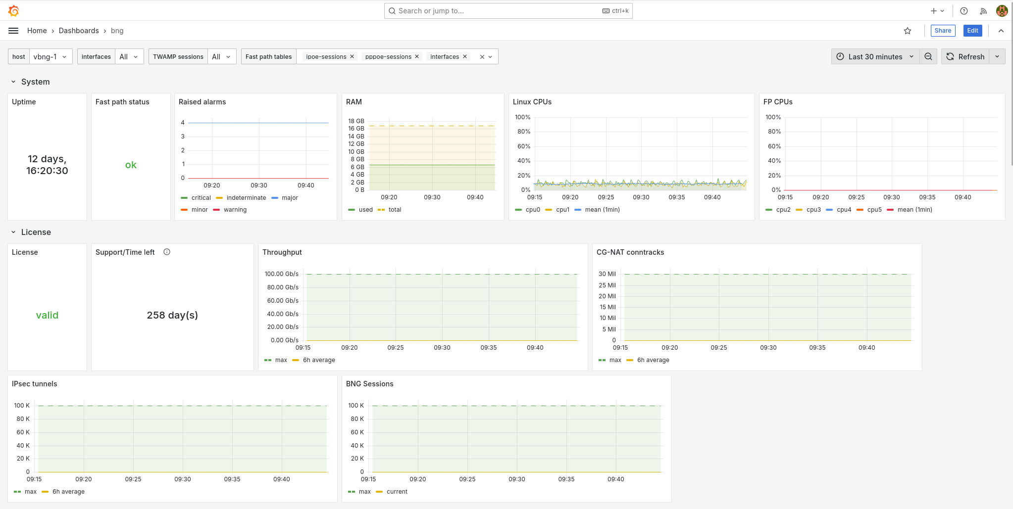
Lower in this BNG dashboard you can get a view on the number of current sessions.
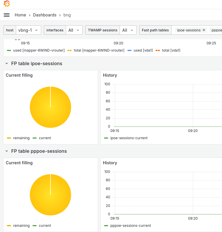
Now your BNG is also sending metrics on fast path & processes health that can be useful in future troubleshooting cases.
5.2. Logs
5.2.1. PPPoE logs
In PPP server, there are three different level of logs activation, the global log level for the whole ppp-server process, and two others for PPP & PPPoE sub-process. Regarding the whole server level, the default level is “error”, but you can choose to have more informations, which can be useful for troubleshooting purposes :
BNG1 running config# / vrf main ppp-server instance pppoeService log-level
                          debug                Display all messages.
                          disable              Disable logging.
                          error                Display error message.  (Default level)
                          info                 Display error, warning and info message
                          warning              Display error and warning message.
Below an example of a normal PPP connections creation :
BNG1 running config# show log
BNG1 systemd-udevd[1462967]: Using default interface naming scheme 'v249'.
Same connection but with debug level :
BNG1 running config# show log
BNG1 main-ppp-server-pppoeService[1462488]: ppp0:cpe1: connect: ppp0 <--> pppoe(90:e2:ba:29:eb:54)
BNG1 main-ppp-server-pppoeService[1462488]: ppp0:cpe1: cpe1: authentication succeeded
In order to obtain clearer informations on ipcp/ipv6cp or lcp negociations you can activate those specific logs :
BNG1 running config# / vrf main ppp-server instance pppoeService ppp verbose true
BNG1 running config# commit

BNG1 main-ppp-server-pppoeService[1462488]: ppp0:cpe1: recv [LCP TermReq id=2]
BNG1 main-ppp-server-pppoeService[1462488]: ppp0:cpe1: send [LCP TermAck id=2]
BNG1 main-ppp-server-pppoeService[1462488]: ppp0:: disconnected
BNG1 main-ppp-server-pppoeService[1462488]: eth0:: send [LCP ConfReq id=fd <auth MSCHAP-v2> <mru 1492> <magic 08c53395>]
BNG1 main-ppp-server-pppoeService[1462488]: eth0:: recv [LCP ConfReq id=1 <mru 1492> <magic c3062c4b>]
BNG1 main-ppp-server-pppoeService[1462488]: eth0:: send [LCP ConfAck id=1]
BNG1 main-ppp-server-pppoeService[1462488]: eth0:: send [LCP ConfReq id=fd <auth MSCHAP-v2> <mru 1492> <magic 08c53395>]
BNG1 main-ppp-server-pppoeService[1462488]: eth0:: recv [LCP ConfAck id=fd <auth MSCHAP-v2> <mru 1492> <magic 08c53395>]
BNG1 main-ppp-server-pppoeService[1462488]: eth0:: send [MSCHAP-v2 Challenge id=1 <a65cec895cd623a176c82ad67da76a>]
BNG1 main-ppp-server-pppoeService[1462488]: eth0:: recv [MSCHAP-v2 Response id=1 <b8fc322abdf56a1d18edbe48777398f9>, <36ec1c4cef5c16a93c89e886903dcfb6b78917e1f7f1fdae>, F=0, name="cpe1"]
BNG1 main-ppp-server-pppoeService[1462488]: ppp0:cpe1: connect: ppp0 <--> pppoe(90:e2:ba:29:eb:54)
BNG1 main-ppp-server-pppoeService[1462488]: ppp0:cpe1: send [MSCHAP-v2 Success id=1 "S=03CFA1ED6F4F54FDAD92DE99E5F452ABE63E4685 M=Authentication succeeded"]
BNG1 main-ppp-server-pppoeService[1462488]: ppp0:cpe1: cpe1: authentication succeeded
BNG1 main-ppp-server-pppoeService[1462488]: ppp0:cpe1: send [IPCP ConfReq id=1 <addr 172.16.255.254>]
BNG1 main-ppp-server-pppoeService[1462488]: ppp0:cpe1: recv [IPCP ConfReq id=1 <addr 0.0.0.0> <dns1 0.0.0.0> <dns2 0.0.0.0>]
BNG1 main-ppp-server-pppoeService[1462488]: ppp0:cpe1: send [IPCP ConfRej id=1 <dns1 0.0.0.0> <dns2 0.0.0.0>]
BNG1 main-ppp-server-pppoeService[1462488]: ppp0:cpe1: IPV6CP: discarding packet
BNG1 main-ppp-server-pppoeService[1462488]: ppp0:cpe1: send [LCP ProtoRej id=255 <8057>]
BNG1 main-ppp-server-pppoeService[1462488]: ppp0:cpe1: recv [IPCP ConfAck id=1 <addr 172.16.255.254>]
BNG1 main-ppp-server-pppoeService[1462488]: ppp0:cpe1: recv [IPCP ConfReq id=2 <addr 0.0.0.0>]
BNG1 main-ppp-server-pppoeService[1462488]: ppp0:cpe1: send [IPCP ConfNak id=2 <addr 172.16.0.4>]
BNG1 main-ppp-server-pppoeService[1462488]: ppp0:cpe1: recv [IPCP ConfReq id=3 <addr 172.16.0.4>]
BNG1 main-ppp-server-pppoeService[1462488]: ppp0:cpe1: send [IPCP ConfAck id=3]
Finally the same connections with pppoe logs activated :
BNG1 running config# / vrf main ppp-server instance pppoeService pppoe verbose true
BNG1 running config# commit

BNG1 main-ppp-server-pppoeService[1462488]: eth0: recv [PPPoE PADI 90:e2:ba:29:eb:54 => ff:ff:ff:ff:ff:ff sid=0000 <Service-Name > <Host-Uniq 37570100>]
BNG1 main-ppp-server-pppoeService[1462488]: eth0: send [PPPoE PADO 02:09:c0:25:4c:42 => 90:e2:ba:29:eb:54 sid=0000 <AC-Name accel-ppp> <Service-Name > <AC-Cookie a6c0829da075b6cddc00e2df3db72f7422a3089c9b7ba84e> <Host-Uniq 37570100>]
BNG1 main-ppp-server-pppoeService[1462488]: eth0: recv [PPPoE PADR 90:e2:ba:29:eb:54 => 02:09:c0:25:4c:42 sid=0000 <Service-Name > <Host-Uniq 37570100> <AC-Cookie a6c0829da075b6cddc00e2df3db72f7422a3089c9b7ba84e>]
BNG1 main-ppp-server-pppoeService[1462488]: eth0: send [PPPoE PADS 02:09:c0:25:4c:42 => 90:e2:ba:29:eb:54 sid=0140 <AC-Name accel-ppp> <Service-Name > <Host-Uniq 37570100>]
BNG1 main-ppp-server-pppoeService[1462488]: eth0:: send [LCP ConfReq id=57 <auth MSCHAP-v2> <mru 1492> <magic 2c3d49da>]
BNG1 main-ppp-server-pppoeService[1462488]: eth0:: recv [LCP ConfReq id=1 <mru 1492> <magic de5b8813>]
BNG1 main-ppp-server-pppoeService[1462488]: eth0:: send [LCP ConfAck id=1]
BNG1 main-ppp-server-pppoeService[1462488]: eth0:: send [LCP ConfReq id=57 <auth MSCHAP-v2> <mru 1492> <magic 2c3d49da>]
BNG1 main-ppp-server-pppoeService[1462488]: eth0:: recv [LCP ConfAck id=57 <auth MSCHAP-v2> <mru 1492> <magic 2c3d49da>]
BNG1 main-ppp-server-pppoeService[1462488]: eth0:: send [MSCHAP-v2 Challenge id=1 <a17387ce8ab74f197dec671bdef1fe15>]
BNG1 main-ppp-server-pppoeService[1462488]: eth0:: recv [MSCHAP-v2 Response id=1 <19931d666b5e59231dea46b1b77f932c>, <4555a5293f5cd0bb229b3850384466c44e3828ad4019e>, F=0, name="cpe1"]
BNG1 main-ppp-server-pppoeService[1462488]: ppp0:cpe1: connect: ppp0 <--> pppoe(90:e2:ba:29:eb:54)
BNG1 main-ppp-server-pppoeService[1462488]: ppp0:cpe1: send [MSCHAP-v2 Success id=1 "S=11EB2A1E2540AEFA79D6D9F15C65A2A1C26B6A8C M=Authentication succeeded"]
BNG1 main-ppp-server-pppoeService[1462488]: ppp0:cpe1: cpe1: authentication succeeded
BNG1 main-ppp-server-pppoeService[1462488]: ppp0:cpe1: send [IPCP ConfReq id=58 <addr 172.16.255.254>]
BNG1 main-ppp-server-pppoeService[1462488]: ppp0:cpe1: recv [IPCP ConfReq id=1 <addr 0.0.0.0> <dns1 0.0.0.0> <dns2 0.0.0.0>]
BNG1 main-ppp-server-pppoeService[1462488]: ppp0:cpe1: send [IPCP ConfRej id=1 <dns1 0.0.0.0> <dns2 0.0.0.0>]
BNG1 main-ppp-server-pppoeService[1462488]: ppp0:cpe1: IPV6CP: discarding packet
BNG1 main-ppp-server-pppoeService[1462488]: ppp0:cpe1: send [LCP ProtoRej id=89 <8057>]
BNG1 main-ppp-server-pppoeService[1462488]: ppp0:cpe1: recv [IPCP ConfAck id=58 <addr 172.16.255.254>]
BNG1 main-ppp-server-pppoeService[1462488]: ppp0:cpe1: recv [IPCP ConfReq id=2 <addr 0.0.0.0>]
BNG1 main-ppp-server-pppoeService[1462488]: ppp0:cpe1: send [IPCP ConfNak id=2 <addr 172.16.0.5>]
BNG1 main-ppp-server-pppoeService[1462488]: ppp0:cpe1: recv [IPCP ConfReq id=3 <addr 172.16.0.5>]
BNG1 main-ppp-server-pppoeService[1462488]: ppp0:cpe1: send [IPCP ConfAck id=3]
5.2.2. IPoE logs
The default log level for IPoE is “error”, equally to PPP, which means no logs if everything’s ok. Anyway you can activate the debug logs to check how it behave in the background :
BNG1 running config# / vrf main ipoe-server log-level debug
BNG1 running config# commit

BNG1 ipoe-server-main[1466958]: send [DHCPv4 Nak xid=2f7a8b87 chaddr=90:e2:ba:29:eb:54 <Message-Type Nak> <Server-ID 10.100.0.2> <Message Session dosn't exist>]
BNG1 ipoe-server-main[1466958]: eth0:: recv [DHCPv4 Discover xid=2a192c73 chaddr=90:e2:ba:29:eb:54 <Message-Type Discover> <Lease-Time 7200> <Request-List MTU,NTP,41,40,Host-Name,DNS,119,Domain-Name,Router,Time-Offset,Broadcast,Subnet>]
BNG1 ipoe-server-main[1466958]: eth0:eth0_90:e2:ba:29:eb:54: eth0_90:e2:ba:29:eb:54: authentication succeeded
BNG1 ipoe-server-main[1466958]: eth0:eth0_90:e2:ba:29:eb:54: send [DHCPv4 Offer xid=2a192c73 yiaddr=10.100.0.11 chaddr=90:e2:ba:29:eb:54 <Message-Type Offer> <Server-ID 10.100.0.2> <Lease-Time 600> <T1 300> <T2 525> <Router 10.100.0.2> <Subnet 255.255.255.255>]
BNG1 ipoe-server-main[1466958]: eth0:eth0_90:e2:ba:29:eb:54: recv [DHCPv4 Request xid=2a192c73 chaddr=90:e2:ba:29:eb:54 <Message-Type Request> <Server-ID 10.100.0.2> <Lease-Time 7200> <Request-IP 10.100.0.11> <Request-List MTU,NTP,41,40,Host-Name,DNS,119,Domain-Name,Router,Time-Offset,Broadcast,Subnet>]
BNG1 ipoe-server-main[1466958]: eth0:eth0_90:e2:ba:29:eb:54: ipoe: session started hwaddr=90:e2:ba:29:eb:54
BNG1 ipoe-server-main[1466958]: eth0:eth0_90:e2:ba:29:eb:54: send [DHCPv4 Ack xid=2a192c73 yiaddr=10.100.0.11 chaddr=90:e2:ba:29:eb:54 <Message-Type Ack> <Server-ID 10.100.0.2> <Lease-Time 600> <T1 300> <T2 525> <Router 10.100.0.2> <Subnet 255.255.255.255>]