2. Configuration
2.2. License
For each vRouter node of this setup, follow the Getting Started guide to provide a minimal Day-1 configuration and install a valid and relevant license.
A valid Turbo CG-NAT Application License is required. Using show license, check
that CG-NAT is activated.
vrouter> show license
Active perpetual license for Virtual Service Router
Current activations 1/1
Connected to license server (last contact 2020-04-22 21:25:00)
Lease is valid until 2020-05-22 21:24:59
Serial number is XXXXXXXXXXXXXXX
Computer ID is OoBA4IqJDHTA7eQmwbRv
License was activated online
Support is valid until 2020-12-31 06:00:00 (standard mode)
Max throughput 20.0G (moving average 0.0G)
CG-NAT activated for 30000000 conntracks (currently used 0)
vrouter>
2.3. Interfaces configuration
Allocate the ports that will be involved in data plane processing to the fast path.
vrouter> edit running
vrouter running config# / system fast-path
vrouter running fast-path#! port pci-b0s4
vrouter running fast-path# port pci-b0s5
All physical and logical interfaces are configured under the main VRF in this example.
vrouter running fast-path# / vrf main
Create Ethernet interfaces, attach them to a port of a NIC and configure IP addresses.
vrouter running vrf main# interface physical lan
vrouter running physical lan#! port pci-b0s4
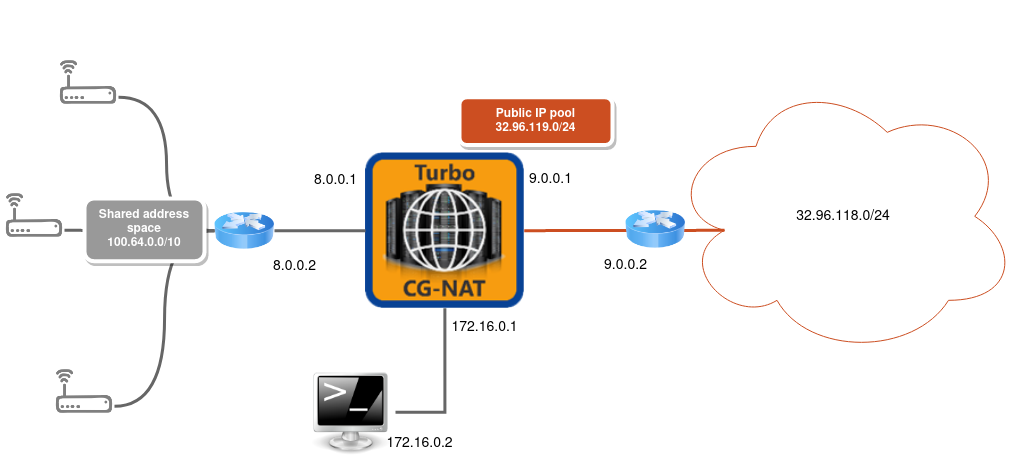
vrouter running physical lan# ipv4 address 8.0.0.1/24
vrouter running physical lan# .. physical wan
vrouter running physical wan#! port pci-b0s5
vrouter running physical wan# ipv4 address 9.0.0.1/24
See also
See the User’s Guide for more information regarding:
2.4. Routing configuration
Configure routes towards the LAN and WAN, plus a blackhole route to drop the incoming public traffic that doesn’t match an existing connection.
vrouter running physical wan# / vrf main routing static
vrouter running static# ipv4-route 100.64.0.0/10 next-hop 8.0.0.2
vrouter running static# ipv4-route 32.96.118.0/24 next-hop 9.0.0.2
vrouter running static# ipv4-route 32.96.119.0/24 next-hop blackhole
2.5. CG-NAT configuration
2.5.1. Pool
A CG-NAT pool contains a list of IPv4 addresses used to change the IPv4 source address and port of a packet.
The vRouter implements a feature called Port Block Allocation. Each time a new user sends a packet through the vRouter, a block of ports is allocated to the user from one of the IP addresses in the pool. Each public IP is divided into blocks of ports, whose size and range is defined in the pool configuration.
Here is an example of pool configuration.
vrouter running static# / vrf main cg-nat
vrouter running cg-nat#! pool mypool
vrouter running pool mypool#! address 32.96.119.0/24
vrouter running pool mypool#! port-range 1024 65535
vrouter running pool mypool#! allocation-mode dynamic-block block-size 256
Note
The ! in the prompt indicates that the current configuration is
invalid. This is because a rule is required to complete the CG-NAT
configuration.
2.5.2. Rule
When using dynamic-snat44 the CG-NAT rule defines the matching criteria to NAT
packets and the pool to use to translate them, replacing the source IP address
and port of the packet with an IP address from the pool and a port from the range.
We can also specify the number of blocks from the pool to associate to each user.
Here is an example of rule configuration.
vrouter running pool mypool#! .. rule 1
vrouter running rule 1#! dynamic-snat44
vrouter running dynamic-snat44#! match
vrouter running match#! source ipv4-address 100.64.0.0/10
vrouter running match#! outbound-interface wan
vrouter running match#! .. translate-to
vrouter running translate-to#! pool-name mypool
vrouter running translate-to# max-blocks-per-user 2
The ! in the prompt has disappeared, meaning that the configuration is now
valid. It can be committed.
vrouter running translate-to# commit
Configuration committed.